Path Planner
As illustrated in the system architectures, the path planner subsystem is in charge of converting discrete behavioral decisions into continuous trajectories which the controller can follow. More specifically, the path planner uses predefined rules to generate trajectories that is cached in the subsystem and then selects tracking poses from the cached trajectory for the controller to follow. In order to allow the RL agent to learn long horizon strategic behaviours, each behavioral request is performed by the path planner for multiple timesteps as opposed to a single timestep. To summarize, whenever a behavior request is sent to the path planner, it firstly generates a trajectory for this request and then executes this trajectory until the termination criteria are met.
As discussed in the earlier section, there are 4 possible behavior decisions that the path planner handles differently. Table # below gives a summary of how those behaviors are handled
| Behavior | Expected Trajectory | Termination Condition |
| Constant Speed | The poses of the trajectory are taken from the center waypoints of the current lane, and the current vehicle speed is used as the reference speed to each tracking pose. | When the action has continued for a certain time period (0.5 second). |
| Accelerate | Like constant speed, the poses are the center line of the current lane, but the reference speeds are generated to increase linearly (constant acceleration). | When the action has continued for a certain time period (0.5 second). |
| Decelerate | Like constant speed, the poses are the center line of the current lane, but the reference speeds are generated to decrease linearly (constant deceleration). | When the action has continued for a certain time period (0.5 second). |
| Lane Change | A trajectory that connects the current vehicle position with the center of the adjacent lane. | When the vehicle drives pass the last pose of the trajectory. |
While the trajectory for constant speed, accelerate, and decelerate behaviors are straightforward, the lane change trajectory requires some kinematics derivation. The trajectory is defined as a cubic spline in the vehicle’s coordinate frame like the equations below.
\[
\begin{array}{l}
x(t)=a_{x} t^{3}+b_{x} t^{2}+c_{x} t+d_{x} \\
y(t)=a_{y} t^{3}+b_{y} t^{2}+c_{y} t+d_{y}
\end{array}
\]
Using the initial and final vehicle poses and velocities to solve for the equations, the parameters ends up being as below.
\[
a_{x}=\frac{2 v_{c u r} t_{d}-2 l_{t r a j}}{t_{d}^{3}}, b_{x}=-\frac{3 a_{x} t_{d}}{2}, c_{x}=v_{c u r}, d_{x}=0 \\
a_{y}=-\frac{2 w}{t_{d}^{3}}, b_{y}=\frac{3 w}{t_{d}^{3}}, c_{y}=0, d_{y}=0
\]
With vcur representing the current vehicle speed, l representing the length of lane change trajectory, w representing the lane width, and td being a tunable parameter that represents the expected lane change duration. td is currently determined with the expression below.
\[
t_{d}=\frac{1.05 \sqrt{l^{2}+w^{2}}}{v_{c u r}}
\]
With all the trajectories defined for each behaviour, the only crucial component left for the path planner is tracking pose selection. The path planner is designed to take the first pose in the trajectory that is in front of the vehicle. This criterion is determined mathematically by the dot product of the vehicle’s unit tangential vector and the vector that goes from the vehicle to the reference pose. A positive result suggests the reference pose to be in front of the vehicle.
Frenet Coordinate System:
For this semester as we scale the complexity of the tasks, we have decided to go with Frenet coordinate system.
The Frenet system represents an object and its trajectory with respect to a reference path, which in the autonomous driving domain is the road or lane that your vehicle is on. The ego vehicle is chosen as the global orgin of the Frenet coordinate frame. This helps in calculating the relative poses of the non-ego vehicle and pedestrians in a more “intuitive” distance metric that also takes into account the features of the road.
The images below elaborate on the application of the Frenet coordinate system in our project in different settings.
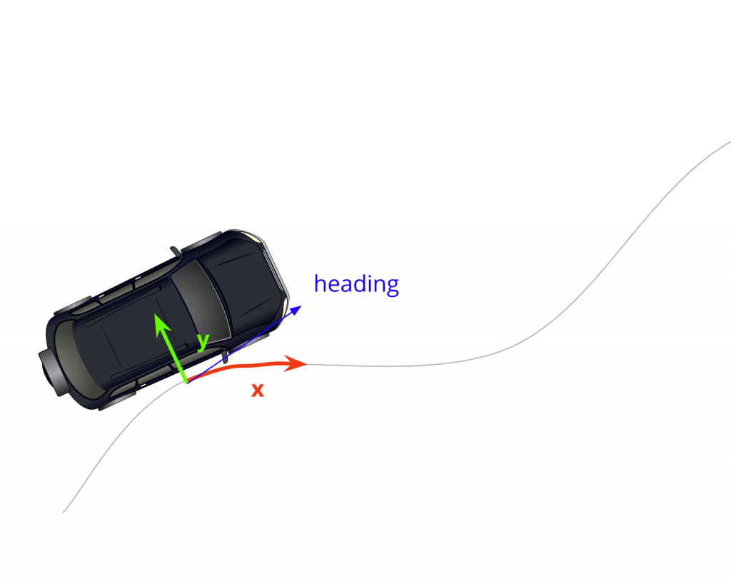
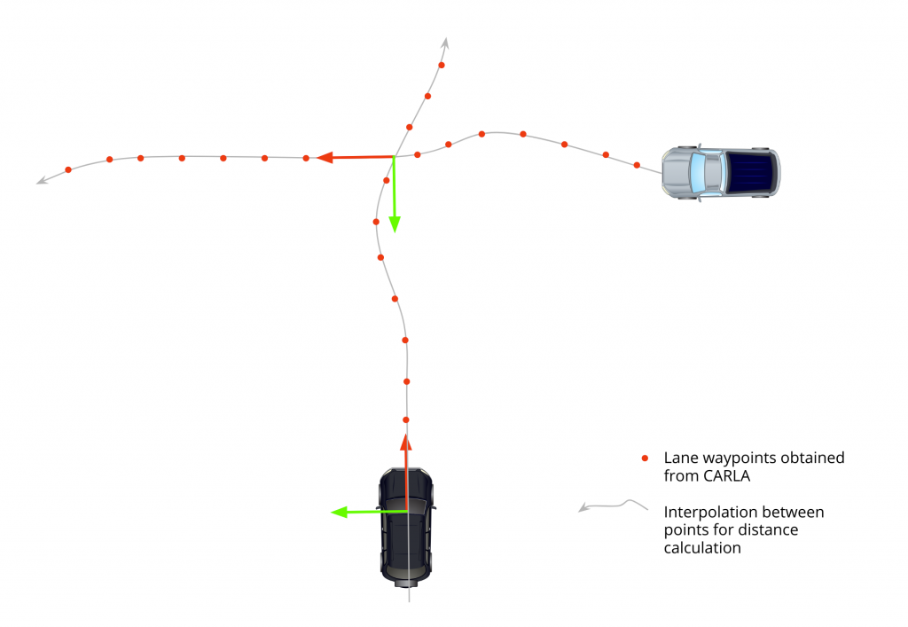
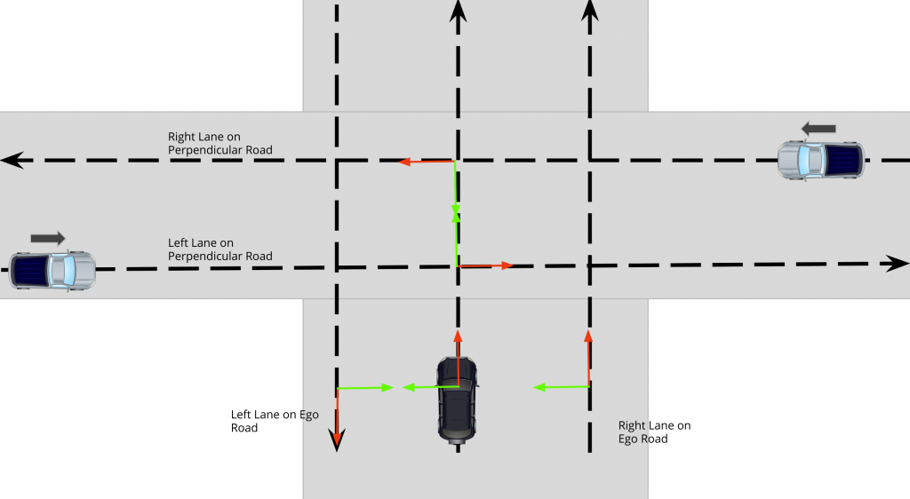
Figure: Frenet coordinate origin frames for an intersection with multiple lanes