We have chosen the RealSense d435i as our stereo camera. This choice was made partly because we had easy access to one of these cameras, and partly because prior work relating to the PitRanger mission had used the same model. The RealSense camera is not space-rated, and its performance does not meet the requirements for the actual mission. For the needs of the MRSD project, however, it is a suitable test platform that gives us the ability to execute our software functionality easily.
One of our first tasks during the spring semester was to familiarize ourselves with the RealSense API. We did this by developing an application that could capture images from the RealSense camera at a variety of different exposures. This was a feature we knew we would need, due to the huge variance of lighting conditions on the moon and the extreme shadows found within lunar pits. By varying the exposure of images captured during pit imaging, we can improve our chances of collecting useful data no matter what.
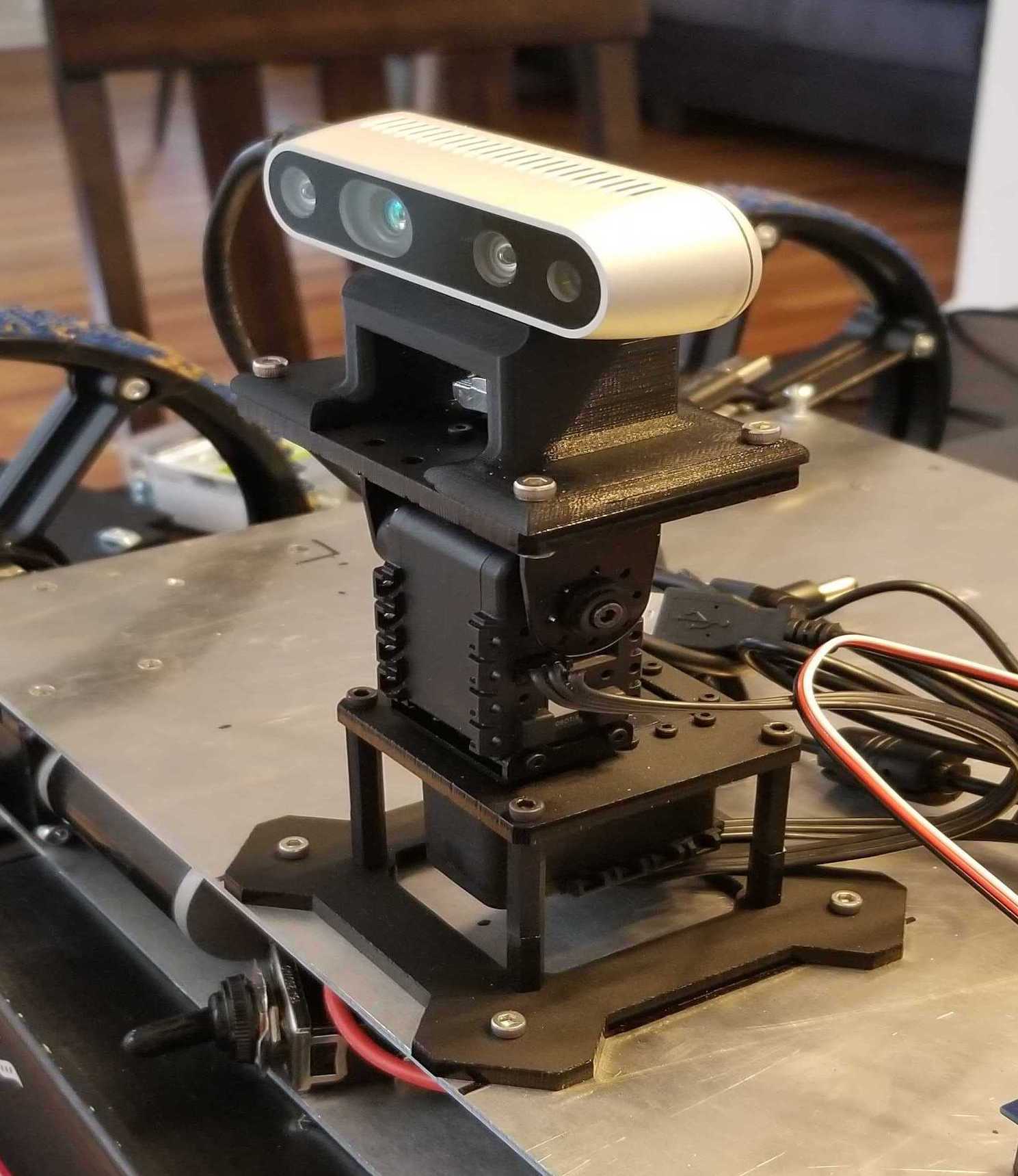
The camera is attached to a pan/tilt mount. When the rover has reached the pit edge, this subsystem orients the camera to a variety of positions and takes images of the pit.
03/05/2020 – Pan-Tilt Mount was identified.
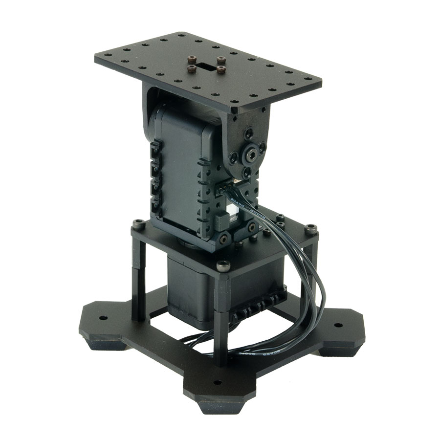
We decided to use the PhantomX pan-tilt mount from Trossen Robotics. This mount uses 2 Dynamixel AX-12 servo motors which can be controlled via the Dynamixel SDK. The image below shows the pan-tilt mount.
03/19/2020 – Dynamixel Control and Camera Mount Complete
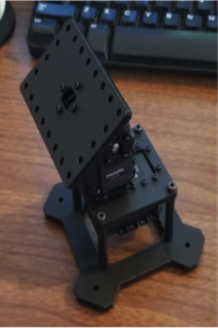
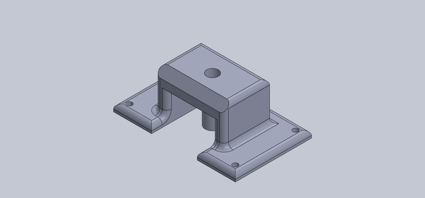
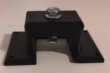
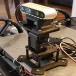
We were able to control the Dynamixel AX-12 motors through a handheld joystick and also designed a camera holder to be fixed on the mount. (This would support the camera on the pan-tilt mount). The image below shows the 3D printed support part on the left, the assembly on in the center and the rover with the assembly mounted on the right.
-

- Pan-Tilt Turret
-
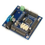
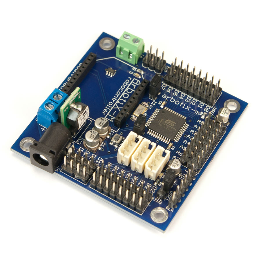
- Arbotix-M Controller
-
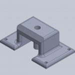
- Realsense Mount
-
- Final Integration
04/12/2020 – Preparing For SVD Demo
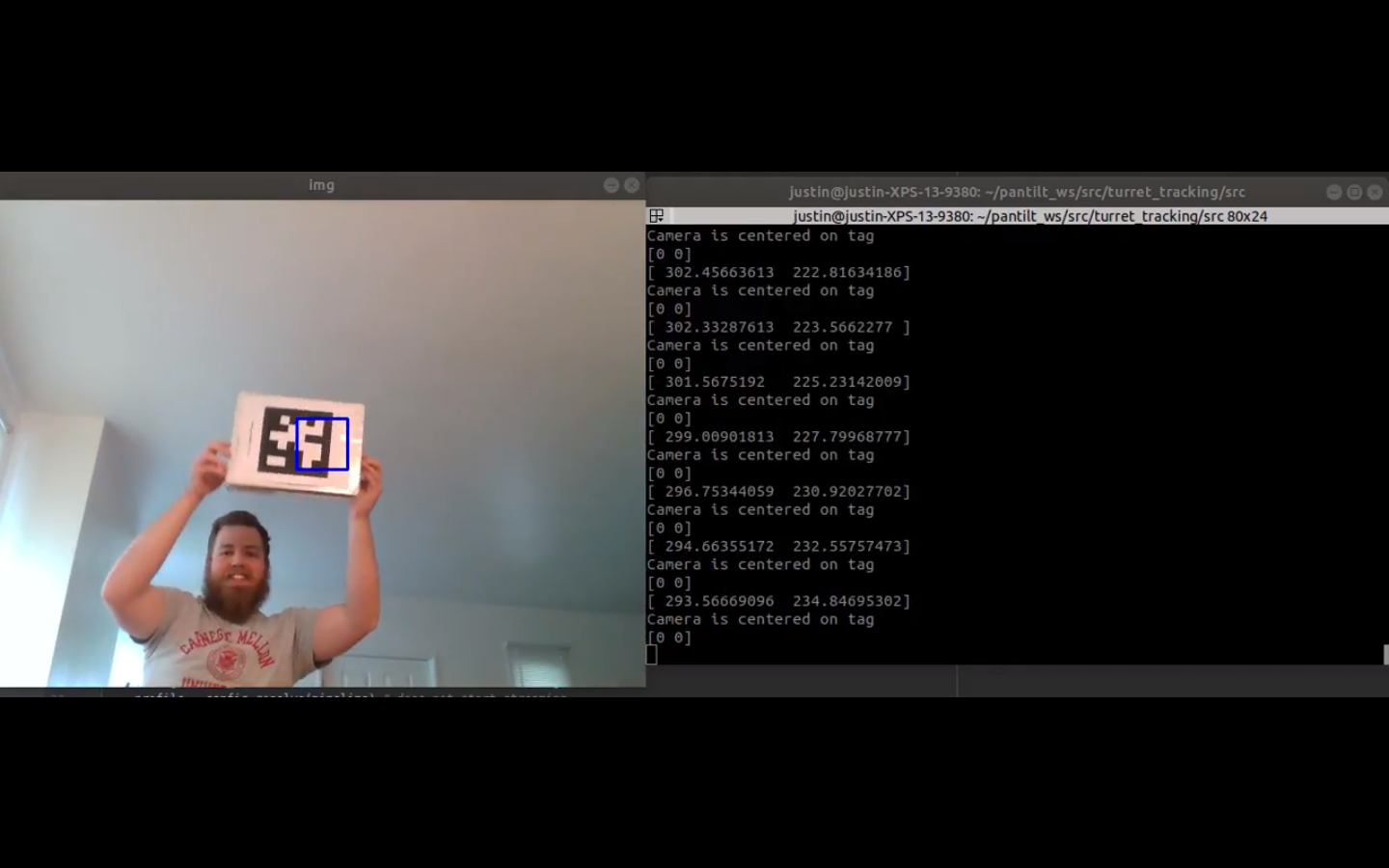
Our validation demonstration for the camera operation subsystem was to have the rover identify an AprilTag marker within the camera images, then actuate the pan/tilt turret in order to center the marker. This was accomplished by calculating a pixel vector from the marker’s position to the center of the image, then translating that vector into proportional motor commands. Once the marker was within 50 pixels of the image center, we would save an image file showing the centered marker. With this method, we were able to move the marker around a room and have the camera continuously track its position.
09/30/2020 – Refactoring Panorama Capture Sequence
For the Spring Validation Demonstration, we had written a simple sequence in the code which would move the camera to nine different pan/tilt angle combinations, and capture an image at each posture. These images were then stitched together into a panorama by a separate program that was run at a later time.
The rover that eventually goes to the moon will need to generate panoramas online, and hard-coded postures for the pan and tilt motors will not be sufficient to ensure total coverage of the pit interior. To that end, we rewrote the code that runs when the rover has reached a vantage point at the pit edge to be more robust and in line with the needs of the mission.
The new panorama capture code can adjust the image capture postures according to the pitch and roll of the rover, in addition to its orientation relative to the pit center. We know that the rover may not always approach the pit exactly head-on and in flat terrain, so the pan and tilt motors must be able to account for this.
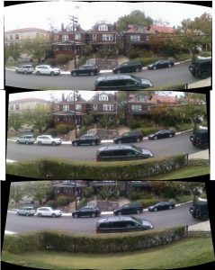
Images taken at each tilt angle setting are stitched together as they are taken into a panoramic image. This process produces wide images showing a horizontal band of the pit interior. These images can then be used by another program running on the rover which constructs a 3D model of the pit.
11/18/2020 – Changing Image Resolution
After our Fall Validation Demonstration, we realized that our system did not meet the requirements for the amount of data captured during the demo. To make sure we met the requirement for FVD Encore, we updated our system to capture high-resolution images. Initially, we captured images at a resolution of 480×640. The update meant that we captured the images at a resolution of 1080×1920. In the tests performed with Blue 2, five images were taken at each of four tilt angles, for a total of 20 images and four panoramas at each vantage point. These changes resulted in our system achieving the specified requirement regarding data capture.