Full System
The system operates the rover in the area around a lunar pit. The system keeps the rover safe by monitoring the rover’s position in relation to the pit edge. The system also generates a plan for capturing images of the interior of the pit from a variety of viewpoints over the course of a series of treks that the rover undertakes from the vicinity of the lander to the pit and back again. At each imaging point, the system aligns the camera with the pit and collects images of the pit from a variety of angles.
Subsystems
Camera Operation
The camera operation subsystem is one of the simpler subsystems within the Pit Navigator project, but it is crucial to the function of many of the other components. For Blue 2, which uses a single camera for both navigation and data collection, the camera operation subsystem must ensure that the camera is constantly in the proper position and feeding images to other subsystems.
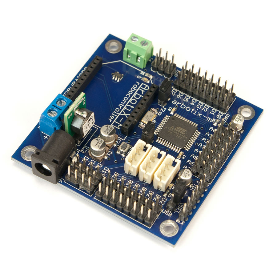
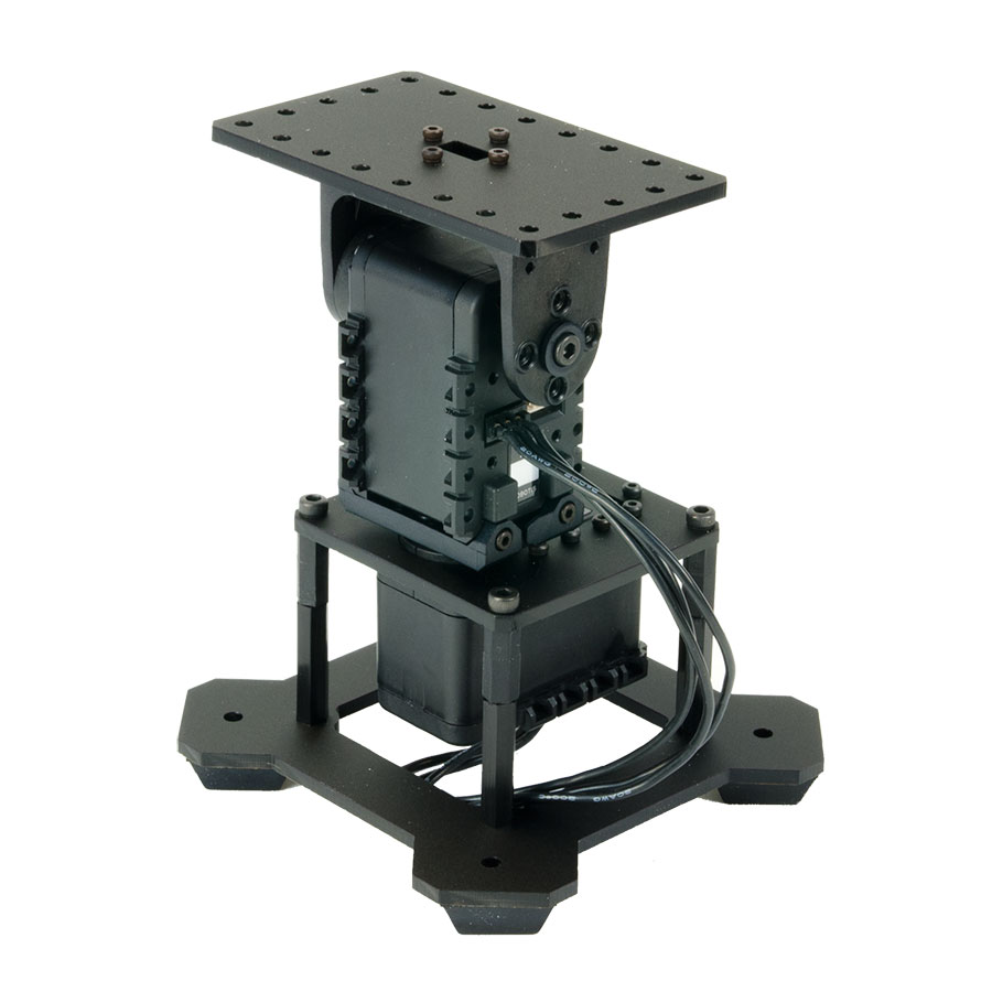
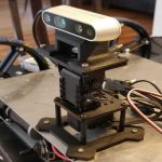
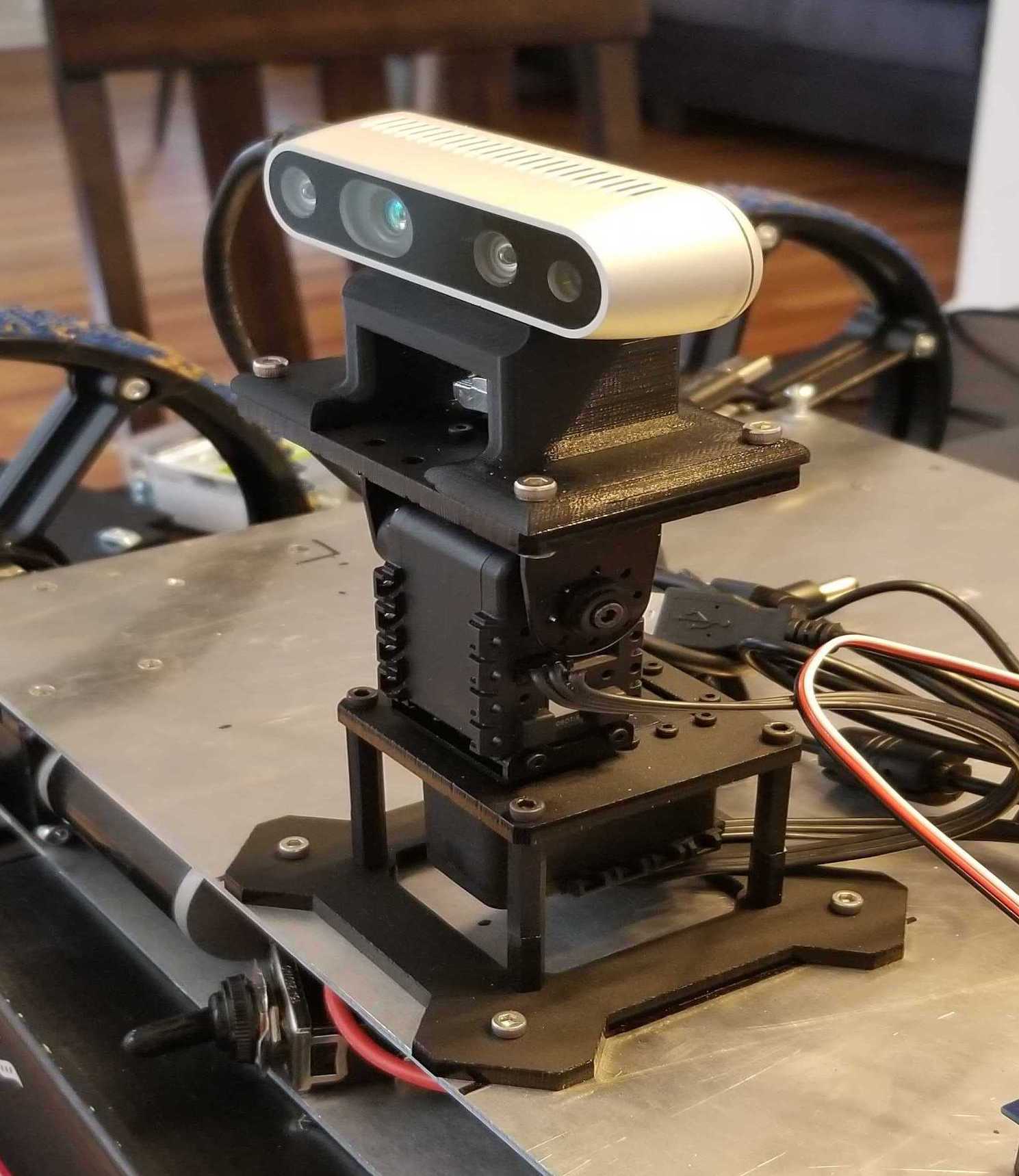
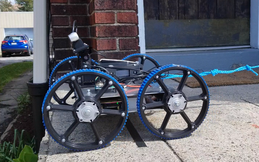
The mechanical components of the camera operation subsystem are a RealSense D435i camera, a PhantomX pan/tilt turret, and an Arbotix-M Robocontroller. The Arbotix-M runs an Arduino-based program that allows it to communicate with the main rover computer. Through a ROS package called arbotix-ros, the main computer can send commands to the Arbotix-M to set the angles of the pan and tilt servos. The RealSense camera is mounted to the top of the turret and connected directly to the main computer via a USB-C cable.
During navigation, the camera faces straight ahead of the rover, angled to capture the terrain that the rover is traversing. The rover will use the camera stereo images and resultant point cloud to generate a local plan to navigate through its environment and avoid obstacles. When the rover nears the pit edge, the brinkmanship subsystem will use the point cloud to drive the rover as close to the pit edge as possible without endangering the rover. The rover will then use the pan/tilt turret to capture images of the pit interior at a range of angles and exposures.
-
- Arbotix-M Controller
-

- Pan-Tilt Turret
-
- Final Integration
This subsystem is effectively complete. The camera and turret have been mechanically and electrically integrated onto Blue 2. Software has been developed to control the exposure of the RealSense camera and transform stereo images into a dense point cloud which can be used by the brinkmanship subsystem. The commands to control the turret position are well-understood and were used to enable the Image Capture and Pit Identification tests during the Spring Validation Demonstration. The Image Capture test in particular applied all portions of the camera operation subsystem, and was used to demonstrate their successful integration.
Brinkmanship
This subsystem maintains information about the robot’s position with respect to the pit. This will involve local brinkmanship checking while the rover is moving to imaging points. The mission plan also includes a plan to assemble and continually update a 3D model of the pit based on images taken by the rover, so this model could be used in the localization process as well.
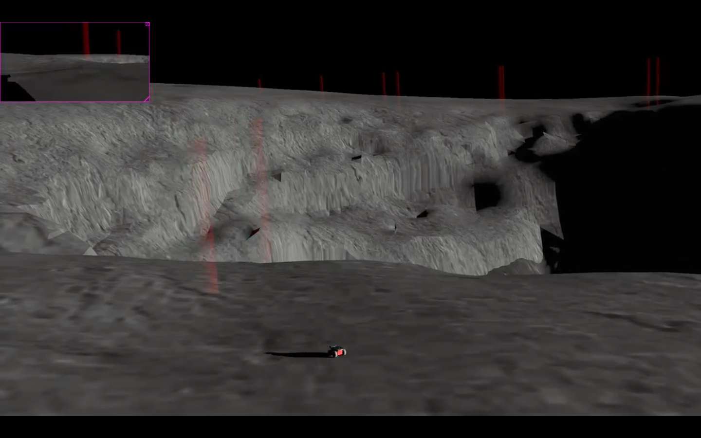
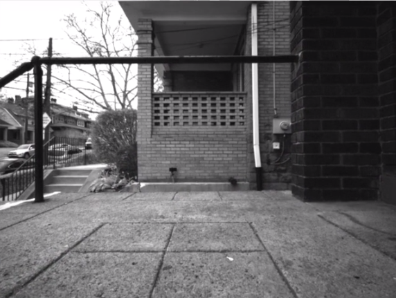
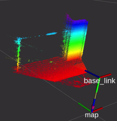
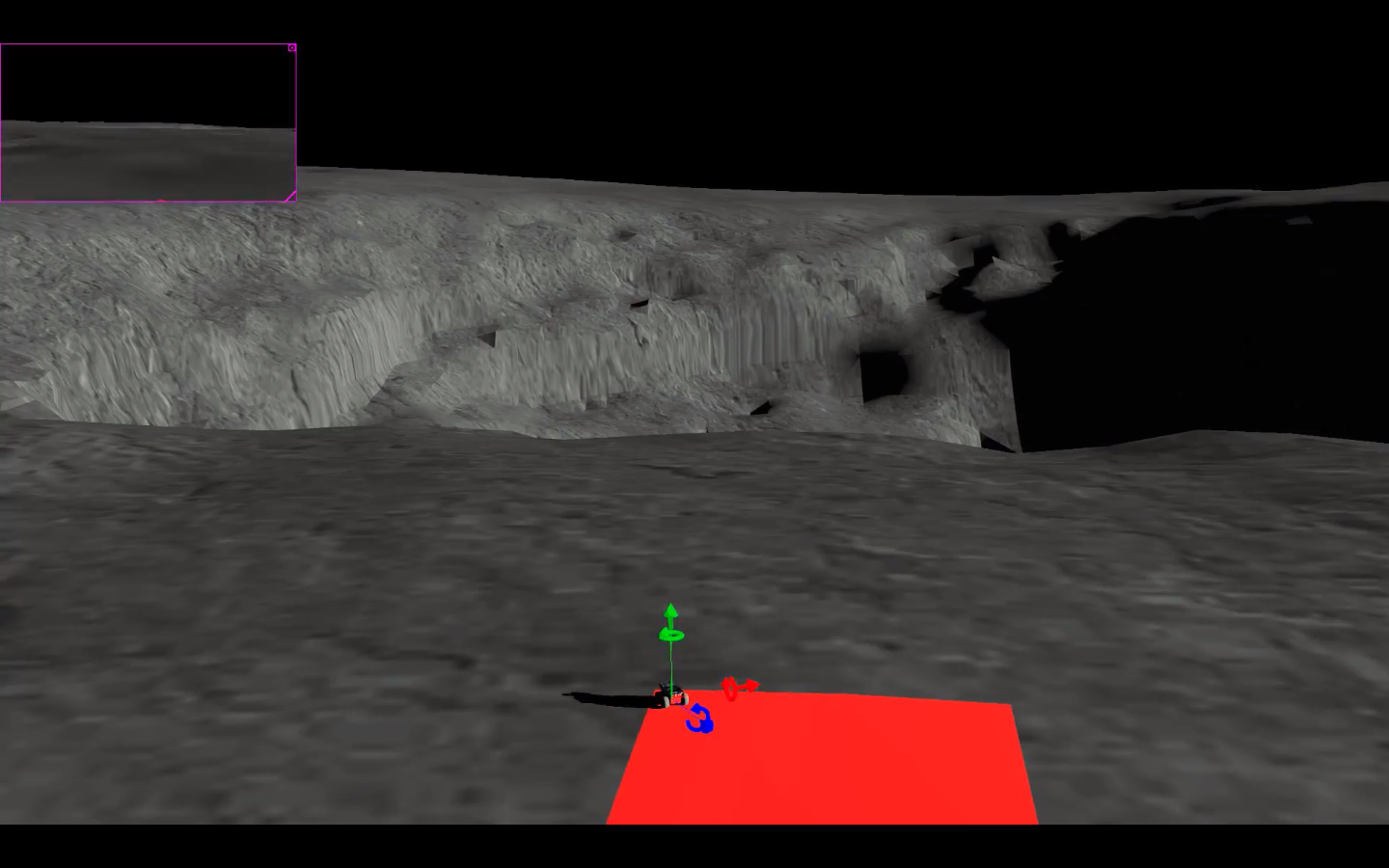
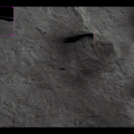
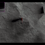
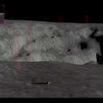
The brinkmanship system will allow the rover to localize itself on a map which is assumed to be pre-calculated from orbital imagery. The idea is that the rover will be able to move to a predefined location near the pit using this map and then will move close to the pit edge with the help of this subsystem. The brinkmanship system currently uses stereo depth reconstruction to get an estimate of the 3D structure of the surrounding. A pit edge is said to be detected when there is an absence of terrain near the rover which is reflected in the 3D reconstruction. This subsystem will trigger an alert signal in such a case and prevent the rover from getting to close to the pit edge.
-

- Rover View (Realsense Camera)
-
- Constructed Pointcloud
-

- Rover Stopping Before An Edge
Risk Assessment and Planning
The planning subsystem is critical to the navigation of the Pit Navigator project. This subsystem is responsible for generating the motor commands and navigating around the environment in a manner that will not cause the robot harm. This system takes in a known global map and a local map of its immediate environment and navigates through the local maps, avoiding known obstacles in the local map. The planning subsystem does this by generating motor commands, known as twist messages, that will safely move the rover to its goal location.
The algorithm that does this known as the TEB local planner. This algorithm was chosen over the base ROS planner because it produces optimal plans, which reduces energy use and increases speed made good by only traversing the shortest possible path. While it can take longer to plan an optimal path, we have found that the trade-off of time spent navigating and time spent planning favors an optimal path in our case when there are few obstacles to avoid.
In our current state, the global map also serves as our local map. The local map is an expanded sliding window of the global map and one pixel is turned into a 50 by 50 square. Normally this local map is added to with /obstacles that represent untraversable terrain, but there are no publishers to that topic at this time. That means that this local map stays empty where the global map is empty and the robot will ignore obstacles that it encounters in the environment due to not perceiving and logging them. The obstacle avoidance algorithm that is not implemented will add the perceived obstacles to this /obstacles topic and the local planner will avoid them. We do not expect errors from the planning subsystem when implementing the obstacle avoidance algorithm once the two are integrated.
These twist messages that the planner outputs are accepted by our simulated robot controller and will move the robot in simulation. The motor controller on Blue2 also accepts twist messages, but porting the planner onto the rover has not been attempted. This generalization to twist messages was made specifically to keep the code mostly rover independent, as it is the ROS standard, and will work on any ROS rover.
The planner was demonstrated in the spring validation test 3. The specific validation criteria for the test that pertained to the ability of the navigation software was navigating to each waypoint to within 0.45 meters or a robot length away. The planner passed this criterion and also currently satisfies the performance requirement of planning an optimal path between waypoints in less than 20 seconds. While the subsystem needs integration, the subsystem itself is nearly complete.
-
- Path Following
-
- Waypoint Traversal 1

-
- Waypoint Traversal 2

-
- Waypoint Traversal 3