Drawings
The CAD model for the end-effector is shown below.
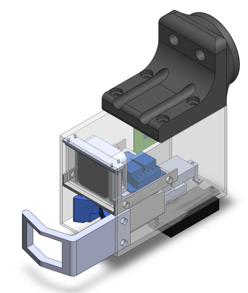
The CAD model for external mechanisms is shown below.

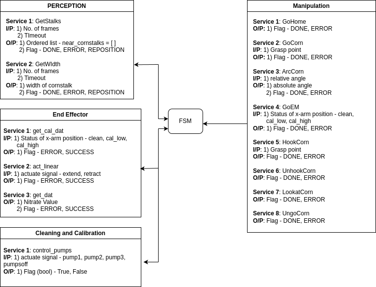
The figure below shows the communication between each node and the FSM
Schematics
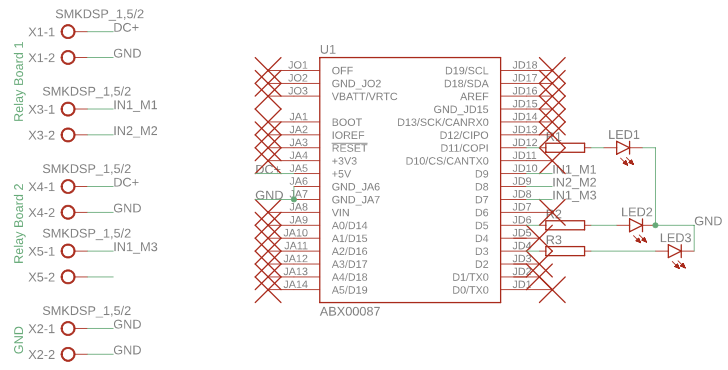
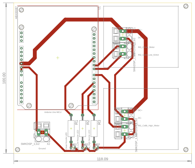
We created a PCB for the external mechanisms to keep the wiring organized and robust. This PCB has header pins to attach an Arduino and it is connected to relays that are wired to the pumps, and LEDs to indicate power. The layout and schematic are shown below:
Datasheets
Intel Realsense D405 Datasheet