Labelling Subsystem
For our labelling subsystem, we utilize two Franka Emika Panda arms equipped with custom suction end-effectors. We have designated specific roles for each: the pick-and-place arm handles the introduction and removal of items from the workstation, while the labelling arm retrieves adhesive RFID tags from a dispenser and applies them to the items.
Suction System
We developed a high-flow suction system powered by a Nessxa air compressor and a vacuum generator. This high-flow configuration is particularly effective for handling RFID labels, as their thin and flexible nature can make achieving a perfect air-tight seal difficult. The system compensates for minor leaks and more easily manipulates the lightweight labels. Initial testing in manual guide mode confirmed the pneumatic system’s ability to retrieve labels from the dispenser and utilize positive pressure for placement, and subsequent autonomous tests have verified the end-effector’s robustness.
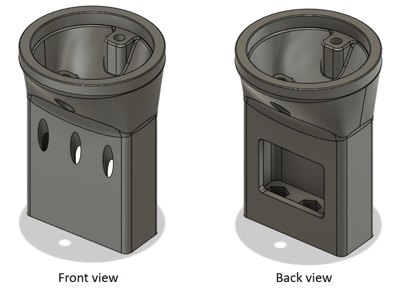
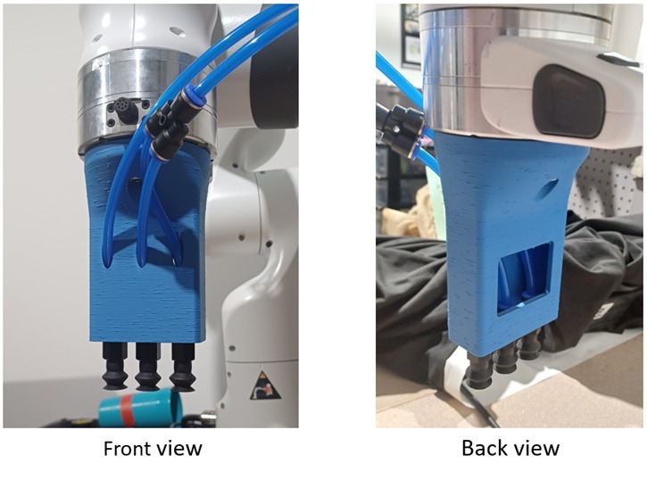
Labelling End-Effector: CAD model (left), 3D print (right)
WWe also integrated a similar end-effector for the pick-and-place arm by leveraging a design from SNAAK, an MRSD team in the 2026 cohort. While this design is generally effective across various shapes and weights, we found that successful grasps on heavier objects require precise alignment with the center of mass. We address these requirements through our automated grasp pose generation logic.


Pick-and-place End-Effector
Motion Planning
The motion planning subsystem is responsible for generating collision-free paths through the labelling workspace for both the pick and place and labelling arms, enabling them to efficiently transport medical inventory and apply labels onto items.
Since the primary goal of this subsystem is to ensure both arms can operate simultaneously within the workstation in a fast, repeatable, and collision-free manner, a waypoint-based planner was adopted for path generation.
For low-level control, inverse kinematics (IK) is applied to each waypoint to obtain the required joint angles, which are then commanded to the onboard Franka controller to execute straight-line motion in configuration space. The joint configurations obtained from IK are additionally verified to be collision-free with respect to static obstacles, with dynamic inter-arm collisions handled separately by the state machine. If a configuration is found to be in collision, it is recomputed until a valid solution is obtained. All possible arm motions were validated to be collision-free, allowing the final system to transport medical inventory and apply labels at speeds significantly faster than would be achievable with more complex, sampling-based planners such as PRMs or RRTs.

Grasp Pose Generation – Input Zone
When an item enters the input zone, the system segments it using a combination of GroundingDINO and SAM. By merging these masks with RGB-D data from an ASUS Xtion PRO Live camera, we generate a point cloud of the top surface to calculate a best-fit plane. The system then computes a grasp pose at the segmentation mask’s centroid to ensure reliable object manipulation.

Segmented Object Masks

Depth Image from Xtion Camera

Object Point Clouds

Computed Grasp Pose
Optimal Label Location – Labelling Zone
To ensure critical information remains visible to the end-user, our system must avoid occluding existing text or labels when applying new RFID tags to item packaging. We address this through a perception pipeline that processes RGB-D data from a top-down ZED Mini camera positioned above the labeling zone. After generating segmentation masks using GroundingDINO and SAM, the system computes a pixel-wise gradient magnitude to identify visual edges on the object’s surface, which will capture text and existing labels. A Euclidean Distance Transform (EDT) is then applied to a gradient image to determine the distance between each non-edge pixel and its nearest edge neighbor.
By identifying local peaks in the EDT and filtering them via Adaptive Non-Maximal Suppression (ANMS), we derive candidate center locations that are intuitively the furthest from any visual clutter. Finally, we project a 40×120 pixel RFID label footprint onto these candidates to verify if a valid orientation exists where the label can be placed without overlapping any detected edges. The system then greedily selects the first valid center point for the final placement.

Original RGB Image

Object Gradient Magnitudes

Local Peaks of EDT

ANMS-Filtered Candidates

Final Label Location
While utilizing gradient magnitude effectively highlights text and pre-existing labels, it also captures high-contrast color transitions and decorative graphics on the packaging. This sensitivity occasionally results in the algorithm being overly cautious or restrictive when identifying placement zones. We are continuing to iterate on this design to improve the system’s robustness and better distinguish critical information from purely aesthetic packaging elements.
State Machine
The system utilizes the ROS SMACH (State Machine and Actionlib) library to manage the complex,concurrent workflows of the logistics and labeling arms. The architecture is designed as a hierarchical state machine, where a top-level concurrence container synchronizes two distinct sub-state machines:
- Logistics Arm (ARM1): Responsible for the ”Pick and Place” cycle – retrieving unlabeled items from the input pile and positioning them in the labeling zone.
- Labeling Arm (ARM2): Responsible for ”Label Application” – retrieving an RFID label from the dispenser and applying it to the localized item.

State Machine Graphic of ORIO System
Error Recovery
The ORIO system incorporates a multi-tier recovery framework to mitigate failure modes including grasp/label drops, IK/motion planning conflicts, and perception errors.
Human-in-the-Loop (HITL) Recovery
Most failures trigger a dedicated GUI intervention request, identifying the error type and workflow location. The interface provides operators with direct hardware control, including manual pneumatic toggling and zone occupancy overrides, allowing them to clear physical jams or reposition items before resuming the state machine from the last valid waypoint.
Autonomous Error Recovery
For failures at the input zone, the system implements an autonomous retry logic to minimize downtime:
- Detection: Real-time vacuum pressure is monitored via the Clearcore controller. A failure to meet the pressure threshold indicates an inadequate seal.
- Resolution: If the item remains in the input zone, the system bypasses the GUI request and automatically re-triggers the perception-pick workflow. By recomputing the grasp pose from a fresh image, the system accounts for any positional shifts caused by the failed attempt, significantly increasing the mean time between failures (MTBF).
Tracking Subsystem
RFID Registration
As items are being labelled, the system simultaneously adds the items’ metadata to a database. Before initiating the system, the user manually enters the target item’s name and expiration date into the system interface. Once the labelling arm picks up a label from the dispenser, a low-power RFID reader on its end-effectory scans the label’s embedded tag. Once the tag is successfully read and placed on an item, a ROS service is called to communicate with the database manager node. The node then associates the scanned RFID data with the user-inputted item details and commits the complete entry into a local SQLite database.

Item Detection & Tracking
Our tracking subsystem utilizes an Impinj R700 RFID reader paired with three RFID antennas and the Impinj ItemTest software.

Impinj R700 RFID Reader
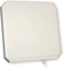
Impinj LHCP Far Field RFID Antenna
Once labelled items are placed on the supply shelves, the inventory tracking subsystem actively
monitors their presence. To account for temporary signal occlusions, an item is only
marked as removed from inventory if it fails to be detected for a set amount of time. While this timeout
threshold was set to 5 seconds during the SVD and SVD Encore for the sake of demonstration speed,
it could be set to 30 minutes, an hour, or several hours depending on the hospital’s needs. Finally,
the backend tracking data is visualized on a system GUI, which provides staff with a real-time list of
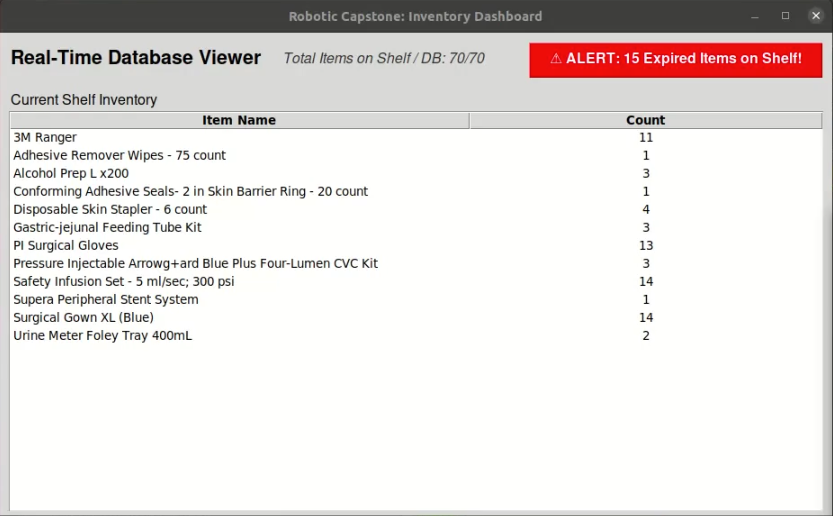
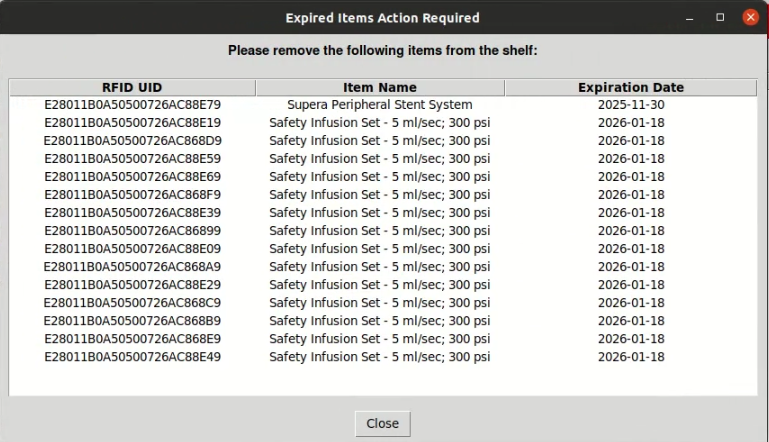
stocked items and automatic alerts for any expired inventory.