February 18, 2026

System Implementation

Project Progress & Assembly Documentation


Electronics & PCB Design
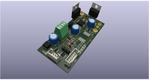
PCB Design Layout
Figure 1: Custom PCB designed for sensor integration and power distribution

Testing & Validation

Treadmill Testing Setup
Figure 2: Human subject testing on treadmill for gait validation
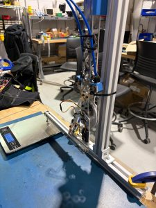
Mechanical Test Bench
Figure 3: Benchtop mechanical testing rig for transmission efficiency validation

Full System Assembly

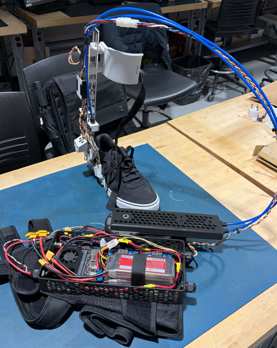
Complete Exoskeleton Assembly
Figure 4: Fully assembled AXilles ankle exoskeleton system

Subsystem Components

Back Brace Assembly
Figure 5: Back Brace Assembly
Motor mounting and cable routing system
Waist Mounting Detail
Figure 6: Waist Mount Detail
Lightweight frame with integrated electronics
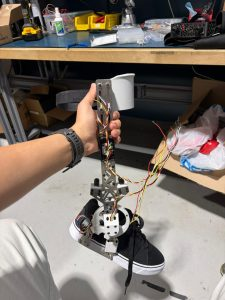
Foot Assembly Mechanism
Figure 7: Foot Assembly
Ankle joint mechanism with embedded sensor suite

Build Process Timeline

Phase 1: CAD Finalization & Manufacturing

We began this semester by finalizing the CAD model and system architecture, then commenced sheet metal part production and 3D printing of structural components.

Initial Assembly Phase 1
Figure 8: Initial mechanical assembly – view 1
Initial Assembly Phase 2
Figure 9: Initial mechanical assembly – view 2
CAD Model and Parts Layout
Figure 10: CAD model verification and component layout planning

Phase 2: Electronics Integration

We implemented a standardized wiring color code for all sensor and power connections to ensure consistency and facilitate troubleshooting:

  • SDA (Data): Yellow
  • SCL (Clock): White
  • VCC (Power): Red
  • GND (Ground): Black
Sensor Wiring
Figure 11: IMU sensor wiring with color-coded connections
Electronics Harness
Figure 12: Complete sensor harness assembly

Phase 3: Electronics Enclosure

The electronics enclosure was designed with aggressive weight optimization while maintaining structural integrity and thermal management capabilities.

3D Printed Enclosure
Figure 13: Weight-optimized electronics enclosure
Component Installation
Figure 14: Jetson Orin Nano and sensor integration
Power Distribution Wiring
Figure 15: Completed power distribution system with buck-boost converters

Phase 4: Force Sensor Integration

Force Sensitive Resistors (FSRs) were prepared with integrated 10kΩ voltage divider resistors and carefully embedded into the shoe insole for ground contact detection.

FSR Preparation
Figure 16: FSR with soldered voltage divider circuit
FSR Installation Underside
Figure 17: FSRs embedded on insole underside (heel and toe positions)
FSR Wire Routing
Figure 18: Signal wires routed through discreet side channel for minimal interference

Phase 5: Final Ankle Assembly

Current Ankle Assembly State
Figure 19: Current state of ankle assembly with integrated sensors and mechanical coupling

Assembly process continues with control system integration and validation testing.