Overview
The docking platform can be divided into three major sub-systems: mechanical, electrical, and sensors:
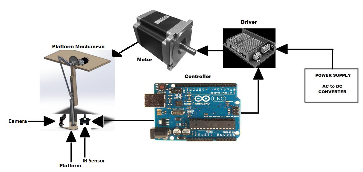 Figure 1 – Dock Design Overview
Physical Structure
The mechanical design is a slider crank mechanism and the platform is connected to the slider. As the crank rotates the slider moves up and down, causing the desired harmonic motion of the platform. A stepper motor is coupled with the crank and can create rotation at different speeds. Based on our performance requirements, the frequency of up-down motion of the platform can vary between 0.15 to 0.3 Hz. This variation is obtained by changing the control input to the stepper motor controller, an Arduino Uno.
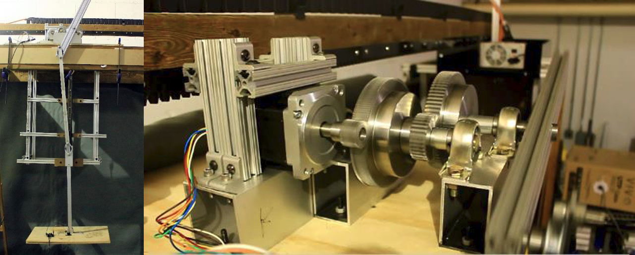
Figure 2 – Docking Platform Structure and Motor/Gear Train
Sensor Package
The motion of the platform is sensed using an IR sensor. The waveform obtained from the motion values (top two in below figure) is used to find the frequency of the platform motion. This information would be subsequently provided to the quadcopter to determine the right instant to dock. The accelerometer values are read in real time through MATLAB and a Fast Fourier Transform (FFT) is performed to obtain the dominant frequency. The FFT of the waveform shown in the lower portion is the result of the process done on the waveform in the top. The dominant frequency is obtained by subtracting the peak in FFT from the maximum range, for example as seen in the lefthand pair, dominant frequency is 50 – 49.8 = 0.2 Hz.
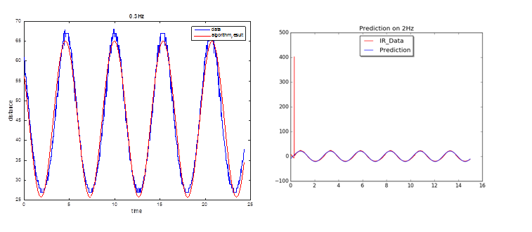
Figure 3 – IR Waveform Detected and FFT processed result
Locking Mechanism
The docking platform has a Velcro pad glued across it (fig 4), which the quadcopter attaches to using another Velcro pad which is attached to the locking mechanism on the quadcopter (fig 5), which is a raised platform with a Veclro pad to lock with and an April Tag for the dock to see so the quadcopter can center and hover ( see below) .
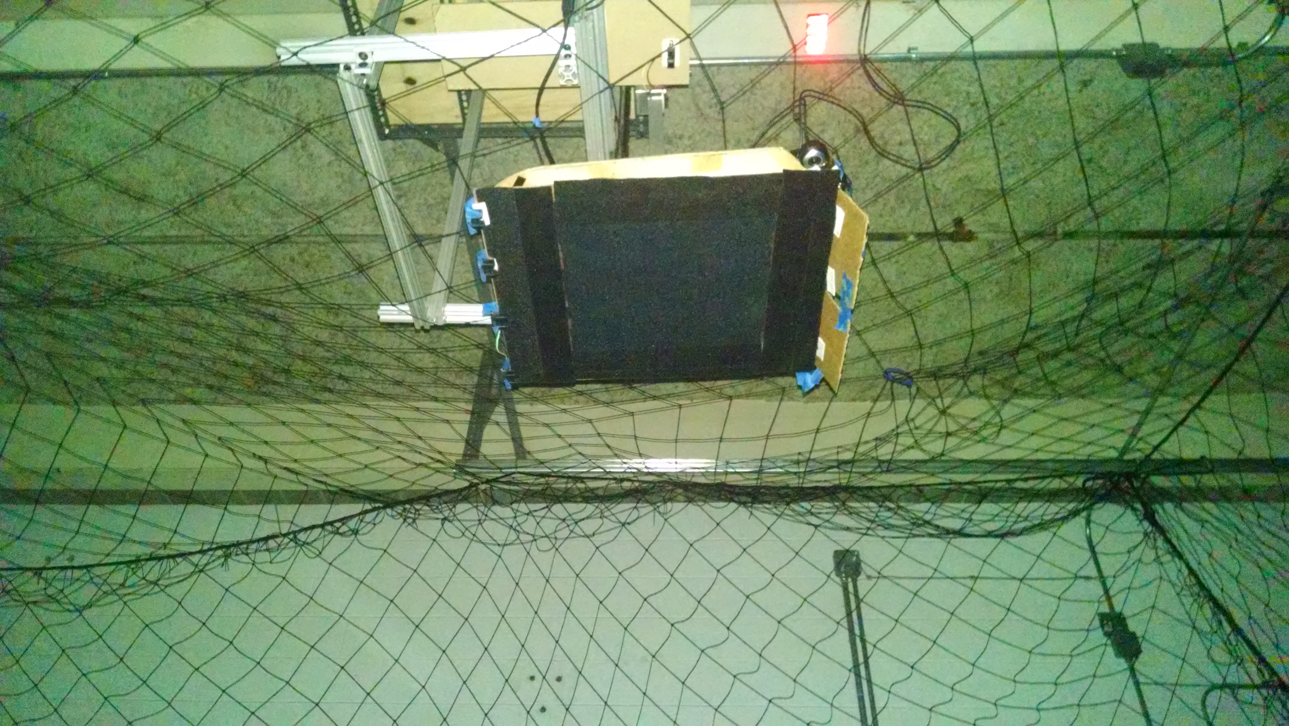
Figure 4 – Docking Platform
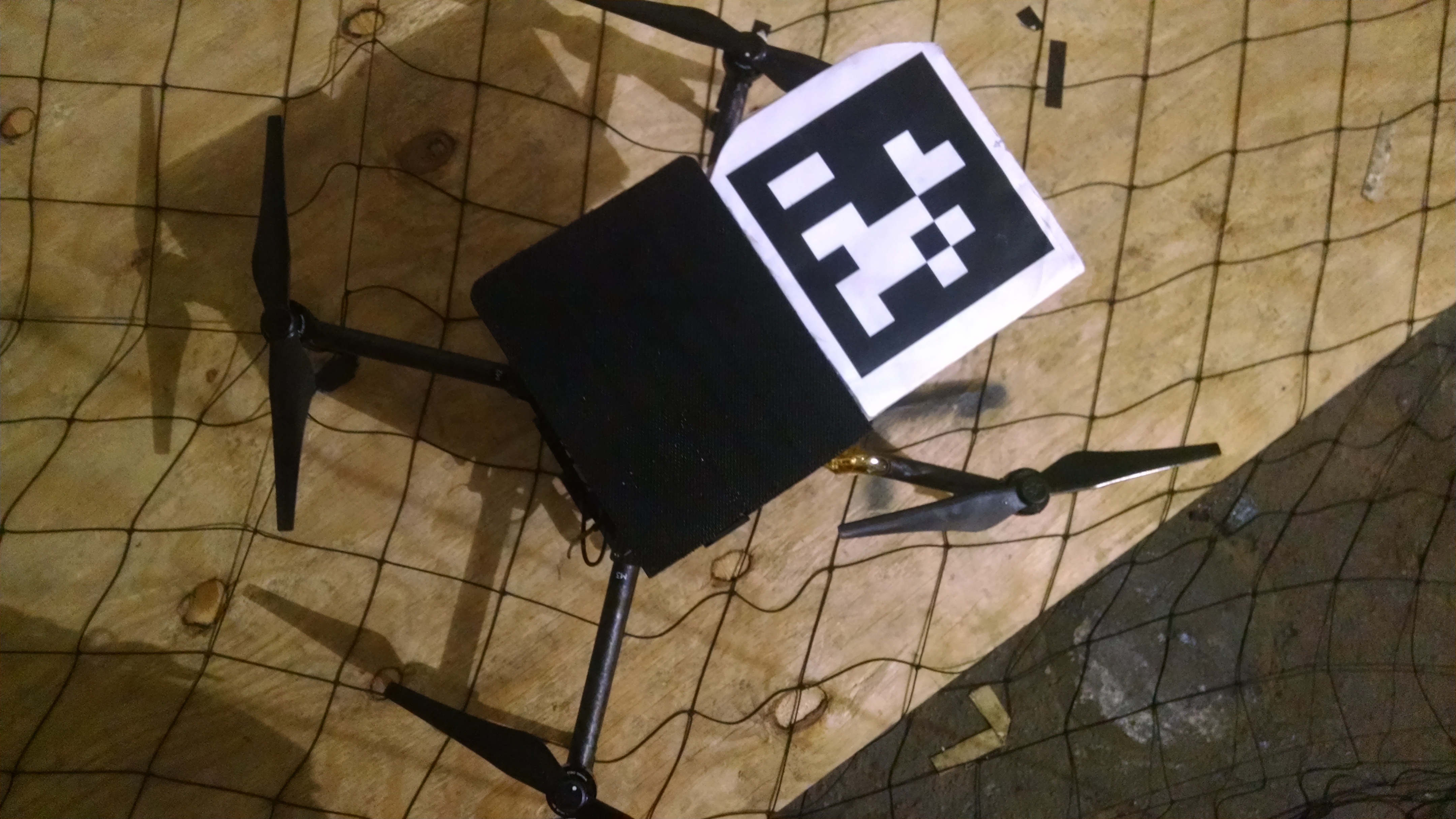
Figure 5 – Quadcopter with Locking Mechanism
When the quadcopter docks, a series of IR sensors (fig 4) record that there is an occlusion and send a message to the Palantir that is in turn used to safely turn off the quadcopter’s propulsion system (flow in fig 6).
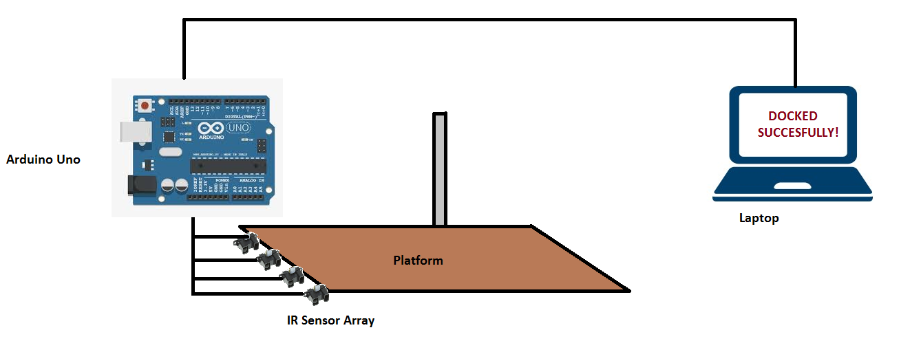 Figure 6 – Dock Detection Flow
Motion Control
The docking platform is constantly moving in the z-direction with a mixture of several simple harmonic motions. An Arduino controls the stepper motor through its driver, sending a number of steps per second which corresponds to the rate at which the crankshaft needs to turn in order to move the dock up and down at a user defined frequency. In addition, the amplitude of the platform’s motion can be controlled by reversing the direction of the motor at set intervals.
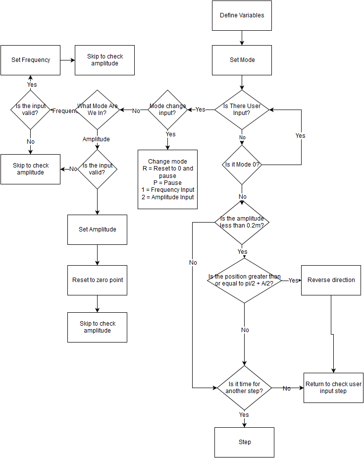
Figure 7 – Flow of Motor Control
Processing – Palantir
The dock now houses our Palantir subsystem(flow in figs 8 and 9), which uses sensors on the dock to predict its motion and a camera on the dock looking down on an April Tag on the quadcopter to send instructions to center it in the XY plane on the dock and have the quadcopter hover a set distance from the lowest point of the dock’s motion. When this has been accomplished, it sends an instruction with a time, velocity, and location and the quadcopter achieves the velocity at the location at the specified time. This has it dock at the platform’s velocity at a safe point in the dock’s cyclical motion. If the dock is moving too fast, the Palantir tells the user, and waits for the dock to slow down before calculating and transmitting data for the quadcopter.
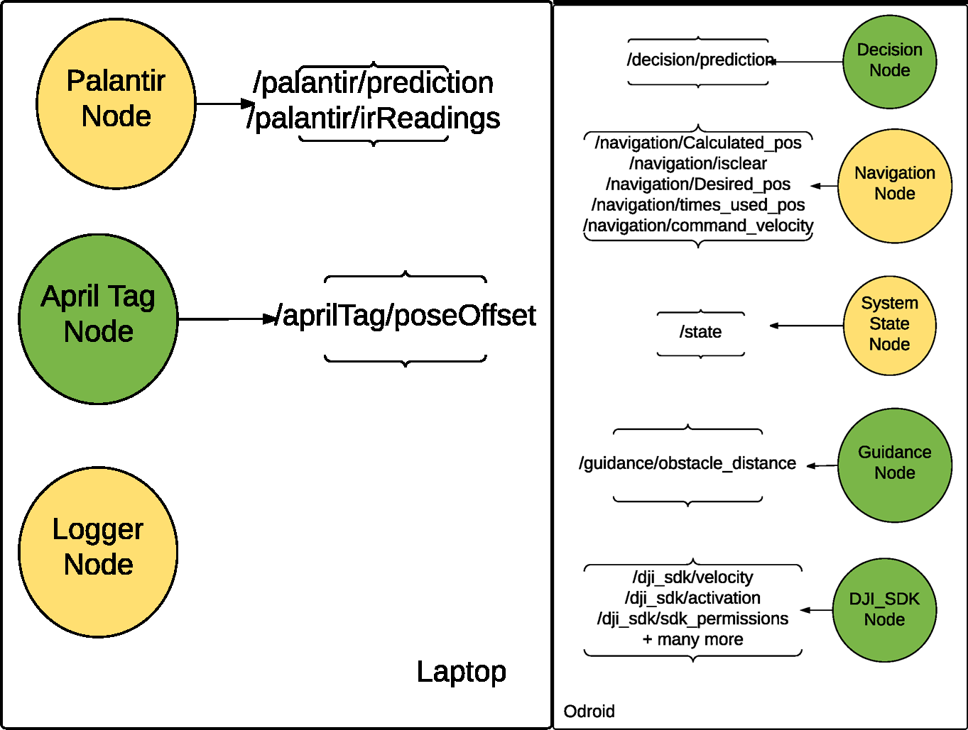
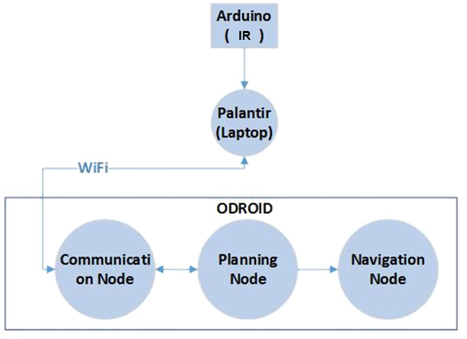 Figure 8 – Communication between Odroid on Quadcopter and IR on Platform with the Palantir on the Dock
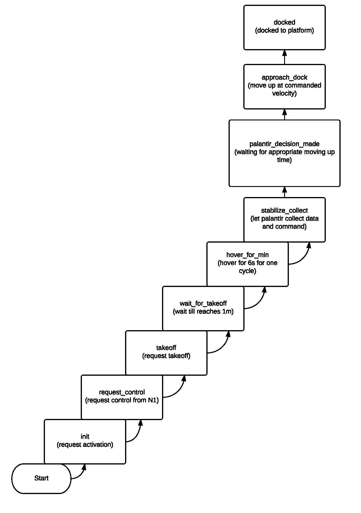
Figure 9 – States Showing The Palantir’s Decision Flow
The Palantir also handles any communication that requires information to be passed or processed between the quadcopter and dock (figs 10-11). This flow has the Palantir subscribe to all the messages coming from the other two major subsystems and having the Dock and Quadcopter subscribe to processed messages with information they require (so far always going in the direction of dock to quadcopter as the dock does not have any function affected by the quadcopter save turning off when docking occurs – a functionality we do not plan on automating).
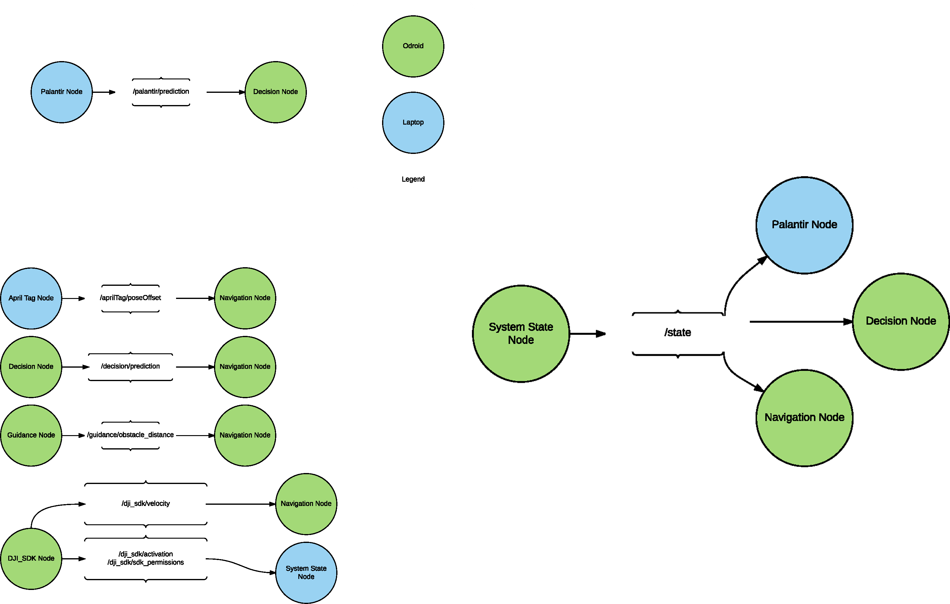
Figures 10 and 11 – Node Architecture and Communication between Subsystems
Computer Vision and April Tag
April Tags are being used to determine the relative pose between the quadcopter and the platform. One or more April tags will be placed on the quadcopter to obtain robust pose estimation. Based on the pose difference, commands will be given to the N1 flight controller. Since we will be testing in indoor flight only, the IMU’s data will be used to close the loop. The April Tag system is being used because it is required that there is an alternate way of ensuring the target position is achieved.
The vision system in the Apriltag node determines roll, pitch, and yaw from the x, y, and z coordinates of the april tag as seen by the webcam as well as using its relative size in the camera’s view to estimate a distance w.
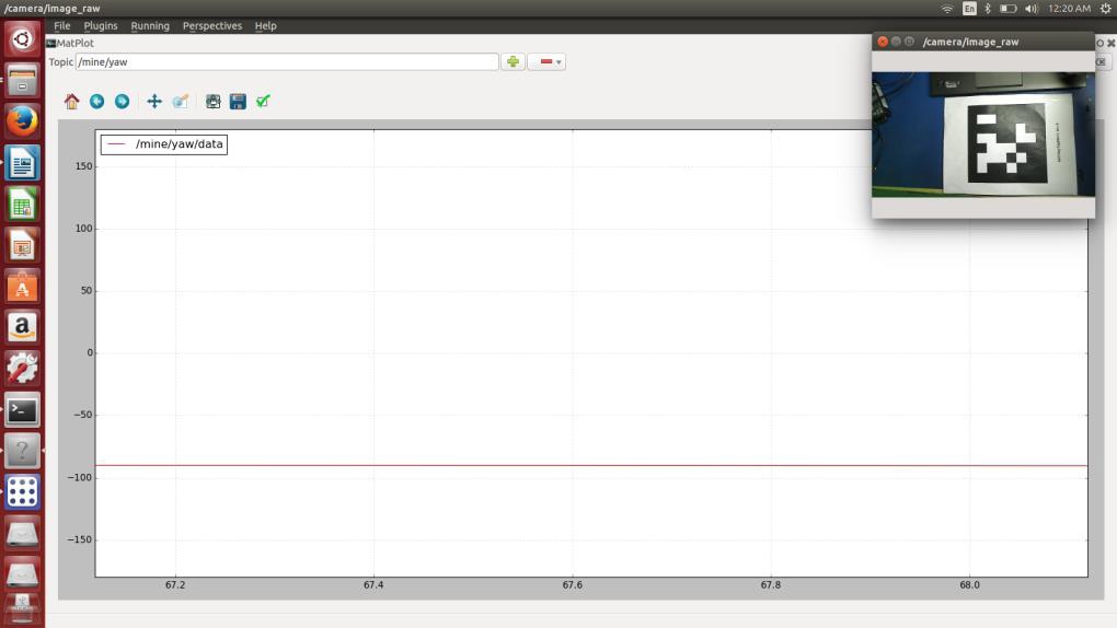
Figure 12 – Example Yaw Plot, Tag Placed on Dock to make estimation of w easier
Control System Power Distribution/Signal Routing
Our dock will have a dedicated circuit board that is used to power the Arduino that will in turn power and control the sensors on board the dock. The board will also route the signals from the sensors to the Arduino. To provide maximum flexibility, the board will be able to handle two accelerometers and two IR sensors, though we only expect to utilize two of a single type of sensor.
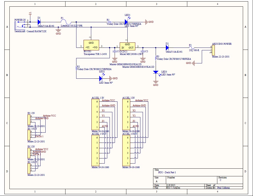
Figure 13 – Board Schematic
To better understand placement of our PDU on the docking platform, we have also produced an output from our board layout to add to the mechanical model so we know where to put it for optimum safety and cable routing.
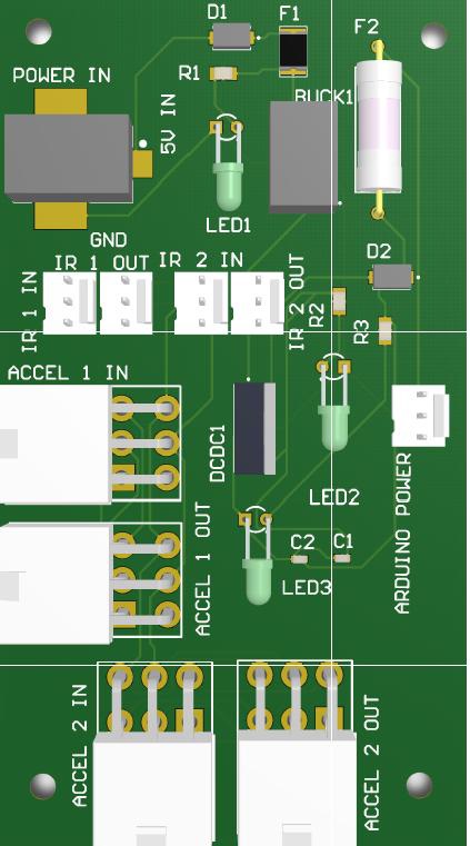
Figure 14 – 3D View of PDU