Lab Demonstrations
10/15/2015 – Demonstration 1 presented by Bishwamoy Sinha Roy
10/22/2015 – Demonstration 2 presented by Paul Calhoun
10/29/2015 – Demonstration 3 presented by Aishanou Osha Rait
11/12/2015 – Demonstration 4 presented by Rushat Gupta Chadha
11/24/2015 – Demonstration 5 presented by Keerthana Subramanian Manivannan
1/28/2016 – Demonstration 6 (Spring Plans and early Unit Tests) presented by Paul Calhoun
2/11/2016 – Demonstration 7 (Centering Quadcopter in XY below platform) presented by Bishwamoy Sinha Roy
2/24/2016 – Demonstration 8 (Centering Quadcopter in XY below platform) presented by Keerthana Subramanian Manivannan
3/16/2016 – Demonstration 9 (Centering Quadcopter in XY below platform) presented by Aishanou Osha Rait
3/30/2016 – Demonstration 10 (Centering Quadcopter in XY below platform) presented by Rushat Gupta Chadha
4/18/2016 – Demonstration 11 (Centering Quadcopter in XY below platform) presented by Paul Calhoun
Schedule
Our Fall schedule was based on getting certain subsystems ready for the Fall Validation Experiment. While this had the benefit of being goal-oriented, it built our schedule backwards rather than forwards, trying to fit subsystems that may have taken a longer time than we were giving them into a schedule intended to get a result at a specific time.
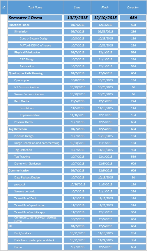 Table 1 – Fall Schedule
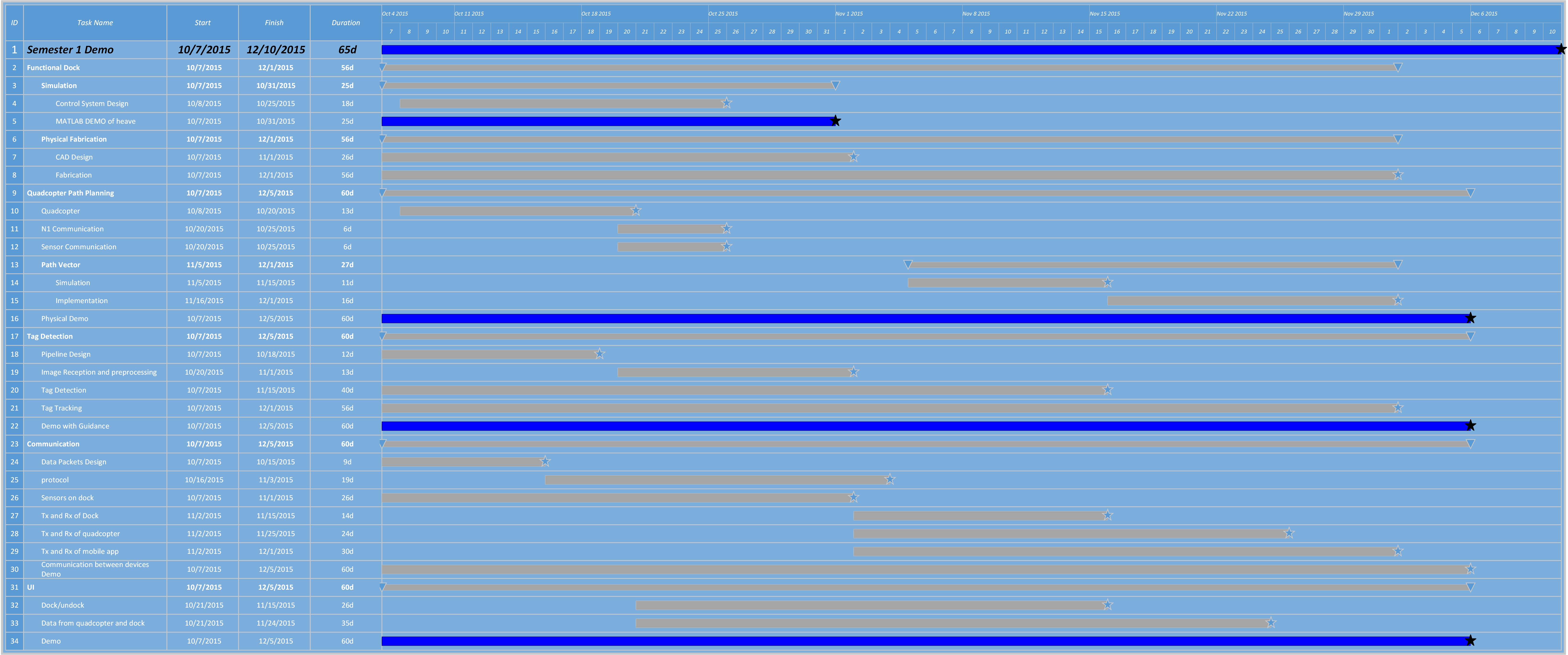 Figure 1 – Gantt Chart of our Fall Schedule
Our schedule is integrated with our progress review (PR) goals, each subsystem we intend to implement or unit we intend to test being a demonstration at the PR.
With our dock functional, our schedule is almost all quadcopter related subsystems being implemented and integrated. Taking into consideration our scope being decreased from the dock having three different waveforms being summed into its harmonic motion to one, and us no longer having graceful undocking as a requirement, we are still one unit test behind schedule. This item, A-to-B navigation has been moved to being our first subsystem to be completed for our first PR. After that, dock motion estimation is our next big hurdle as it may be simple but may also turn out to need different sensors or a new approach. Finally we will begin on navigation and docking starting with a stationary platform and then a moving one, concurrent with development of our user interface. We are including two PRs – approximately a month and a half – for integration, logistics delays, unexpected failure modes, and other slips. While this may at first appear as if it leaves us nothing to demonstrate between PR 10 and SVE, we will be restoring de-scoped requirements to the project if there are no significant delays.
| Timeline | Progress Review | Planned Milestone | Actual Milestone | Presenter |
| Late January | PR 7 | • Quadcopter motion from Point A to B, Preliminary
• Palantir Functionality – Fitting and Communication |
• Quadcopter motion from Point A to B, Preliminary
• Palantir Functionality – Fitting and Communication |
Paul Calhoun |
| Mid-February | PR 8 | • Determine position and velocity of platform using CV and sensors
• Quadcopter maintains hover point in XY Plane |
• Determine position and velocity of platform using CV and sensors
• Quadcopter maintains hover point in XY Plane |
Bishwamoy Sinha Roy |
| Late February | PR 9 | • Stabilization of Quadcopter under the Platform
• Docking to the platform with the Nicadrone |
• Stabilization of Quadcopter under the Platform
|
Keerthana Subramanian Manivannan |
| Mid-March | PR 10 | • Achieve docking on moving platform | • Quadcopter hovers at a fixed point below platform
• Palantir outputs correct curve fit to Dock Data |
Aishanou Osha Rait |
| Early April | PR 11 | • Testing and refinement
• All dock motions produce correct outputs – Docks or refuses to dock |
• Quadcopter docks to stationary platform
• Dock detects successful docking action |
Rushat Gupta Chadha |
| Mid-April | PR 12 | • Testing and refinement
• Quadcopter lands within time limits and with 80% success rate |
• Achieve docking on moving platform
• All dock motions produce correct outputs – Docks or refuses to dock |
Paul Calhoun |
Table 2 – Spring Schedule
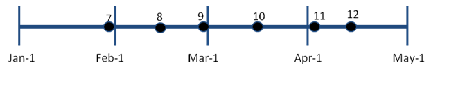
Figure 2 – Spring Time Line
To support this, we have 24 unit tests which are detailed in our test plan. Each one corresponds to a line on our schedule below.
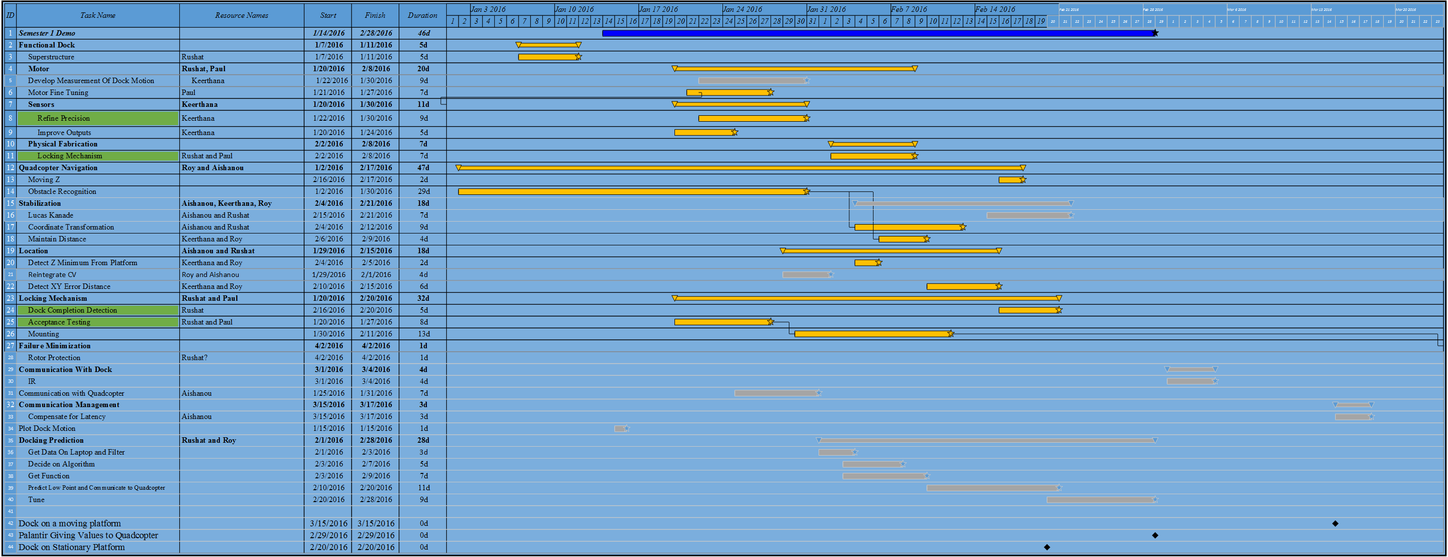
Figure 3 – Spring Schedule
We’re currently doing well in keeping up with our planned milestones. The locking mechanism was delayed, which cascaded down our critical path, but we are still on track to meet all our SVE goals.
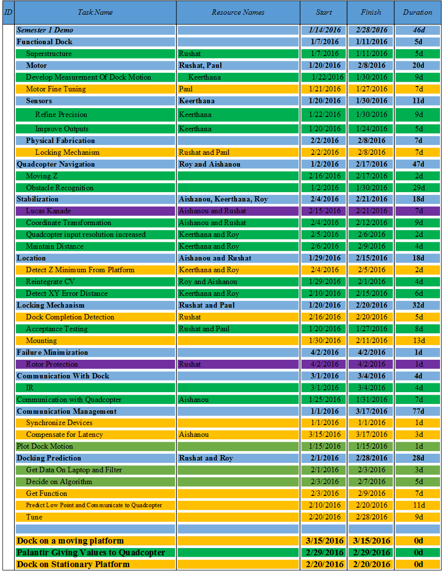
Figure 4 – Spring Schedule Tracking (Green = Met On Time, Orange = Met Late, Red = Unmet and Late, Purple = No longer being developed)
Test Plan – Spring
Our full test plan including equipment, configurations, and unit tests can be found at our TeamE Spring TestPlan
Spring Validation Experiment
Location: Newell-Simon Hall, Level B
Equipment to be used: DJI Matrice100, Guidance, Designed Platform, Power Supply, Laptop
Capabilities Proved: System determines correct moment to dock, quadcopter docks with platform without collision
Test starting setup: Quadcopter will be on the ground within a 0.25 meter distance from the platform.
Full System Test/Check
Action: Place the quadcopter on the ground within .25 m from the platform, start engines, begin autonomous hover
Action: Turn on the power to platform and enter a frequency for platform motion on the Palantir within range of 0.15 to 0.3 Hz)
Result: The frequency of platform motion changes to the input frequency
Result: Motion is detected by sensors and graph is plotted on the Palantir showing that the motion is the desired frequency waveform (i.e. frequency detected is the frequency entered by the user), the lowest point is found by the Palantir
Result/Autonomous Action: The quadcopter will hover a fixed distance below the lowest point platform (within 5 cm accuracy in X-Y plane)
Result: The Palantir will give the quadcopter the time, velocity, and location it must reach to dock. At the appropriate time, the quadcopter will perform the maneuver required, using pressure to ensure a secure connection of the Velcro.
Result: The dock’s IR sensors will transmit a flag to the Palantir telling it that docking is successful and the quadcopter will begin to power down propulsion.
Metric: The velocity of quadcopter with respect to the platform will be less than 50 cm/s when quadcopter is moving up towards the platform
Metric: Quadcopter will remain securely attached to the dock with its propulsion turned off for at least 30 seconds.
Metric: Repeat above steps 5 times with different starting positions and different frequencies of platform. Docking should be successful 80% of the times.
Figure 5 – Spring Test Plan Flow
Test Plan – Fall
Fall Validation Experiment
Test Facility
Location: NSH Level B, Carnegie Mellon University
Equipment: Quadcopter, Monocular camera, Designed Platform, Laptop, 30V DC power supply
Size of Test Area: 5m x 8m x 4m
Setup:
PLATFORM: The supply to the platform will be turned on. The laptop with serial monitor will be connected to the Arduino board.
QUADCOPTER: The quadcopter will be placed at any arbitrary position within the test area. Smartphone is connected with DJI Go App to the remote controller. The quadcopter and remote controller are powered on. P2P connection will be established between the quadcopter’s SBC and the laptop via WiFi. SSH into the onboard SBC’s shell
Process:
PLATFORM:
- Input the frequency of platform motion from the laptop between 0.15 to 0.3 Hz
- Platform motion will be detected by the sensors and graphs will be plotted on the laptop showing harmonic motion
QUADCOPTER:
- Roslaunch the master.launch file in the dji_code ros package
- The quadcopter will prompt the user via the laptop whether to commence or not – type y for the quadcopter to lift-off and hover
- Once hover has been achieved, it will prompt you to either TRACK AprilTag or MOVE.
- Choose MOVE and it will prompt you for a X,Y position.
- Enter a X,Y position within 5m of starting position
- The quadcopter will move and land to the allocated position within +/- 3m error
- Place the quadcopter above the AprilTag, lift off again and choose TRACK AprilTag
- If the AprilTag moves within 0.4m of the previous position the quadcopter should move with it
- During any of the above tests, inputs from the remote control will override all other commands
- Repeat steps 4 to 9 five times to test repeatability
Success criteria:
PLATFORM: The user input frequency (0.15 to 0.3 Hz) would match the frequency detected by the sensors within an accuracy of 0.05 Hz
QUADCOPTER:
Figure 1: Environment Layout
- Place the quadcopter at starting point as shown in Figure 1
- Enter (2,3) as the X,Y coordinate in step 6. The quadcopter will land at the target position within 0.3 m accuracy. Circle of 1.6 m will be made around the target position to check the accuracy of landing
- Test for different X,Y target positions within 5m from starting position. Accuracy of 0.3m will be achieved 70% of the time
- The quadcopter will follow and hover over the AprilTag when the AprilTag is moved<= 0.4m
Fall Unit Tests
| Item | Location | Method | Measurement |
| April Tag Detection | Laptop and Bench | Tested in varying lighting conditions and changed update times. | Looked for detection of April Tag on screen. |
| April Tag Detection | Odroid and Bench | Tested in varying lighting conditions and changed update times. | Looked for detection of April Tag on screen. |
| Dock Frequency Control | Dock Assembly | Run frequency input program | Accelerometer on dock platform to find error between input and output |
| Motor | Bench | Run motor at varying speeds to find stepper frequency | Stopwatch checks and watching the shaft rotation to see how often it made a full turn |
| Motor gears | Bench | Run motor with gears attached | Stopwatch and observation to find error between input and output |
| Quadcopter Hover | Laptop simulation | Simulated code for hover | Whether the simulated quadcopter held position in XYZ |
| Quadcopter Hover | Quadcopter Test Facility | Ran code on Odroid attached to quadcopter | Whether the quadcopter holds position in XYZ |
| Quadcopter Position Control | Laptop simulation | Simulated code for A to B motion | Whether the simulated quadcopter moves from the starting position to the designated end position |
| Quadcopter Position Control | Quadcopter Test Facility | Ran code on Odroid attached to quadcopter | Whether the quadcopter moves from the starting position to the designated end position |
Table 3 – Fall Unit Tests
Parts list
| Part | Subsystem | Cost | Funding Source | Quantity |
|---|---|---|---|---|
| DJI Matrice M100 | Quadcopter | $3300 | Sponsor | 1 |
| Guidance System | Quadcopter | $1000 | Sponsor | 1 |
| Guidance Connector Kit | Quadcopter | $79.00 | Sponsor | 1 |
| TB48D Battery | Quadcopter | $199.00 | Sponsor | 1 |
| Spare Propellors | Quadcopter | $15 | Sponsor | 10 |
| Dock Motor | Dock | $215.00 | CMU | 1 |
| Dock Motor Driver | Dock | $488.00 | CMU | 1 |
| Accelerometer | Dock | $20.00 | CMU | 2 |
| Nicadrone | Quadcopter | $90.00 | CMU | 2 |
| Spare Propellors | Quadcopter | $20.00 | CMU | 2 |
| ODROID-XU4 | Quadcopter | $74.00 | CMU | 1 |
| ODROID-XU4 Case | Quadcopter | $2.70 | CMU | 1 |
| WiFi Module | Quadcopter | $8.00 | CMU | 3 |
| DC Plug Cable Assembly 5.5mm L Type | Quadcopter | $1.25 | CMU | 1 |
| USB to TTL Serial Cable | Quadcopter | $9.95 | CMU | 1 |
| AC/DC Adaptor Charger Cord | Quadcopter | $6.99 | CMU | 3 |
| Steel Drive Shaft | Dock | $24.09 | CMU | 2 |
| External Retaining Rings | Dock | $8.25 | CMU | 1 |
| Steel Mounted Ball Bearing | Dock | $12.69 | CMU | 3 |
| Key Stock | Dock | $4.53 | CMU | 2 |
| Flange Mounted Bearing | Dock | $27.39 | CMU | 3 |
| Shaft for Crank | Dock | $8.30 | CMU | 4 |
| Brass Standard Key Stock | Dock | $1.78 | CMU | 1 |
| Black-Finish Steel External Retaining Ring | Dock | $10.13 | CMU | 1 |
| Frelon-Lined Sleeve-Bearing Carriage | Dock | $41.44 | CMU | 1 |
| Guide Rail, 15mm Wide, for Frelon-Lined Sleeve-Bearing Carriage | Dock | $93.80 | CMU | 1 |
| Matrice Landing Gear Kit | Quadcopter | $19.00 | CMU | 1 |
| Docking Mechanism Electronics | Dock | $393.87 | CMU | 1 |
| Quadcopter Leg Spares | Quadcopter | $99.00 | CMU | 4 |
| Quadcopter electronics battery | Quadcopter | $33.42 | CMU | 1 |
| Quadcopter electronics battery charger | Quadcopter | $49.73 | CMU | 1 |
| Quadcopter electronics battery cable | Quadcopter | $10.60 | CMU | 3 |
| Linear Regulator | Quadcopter | $8.04 | CMU | 3 |
| Quadcopter electronics PCB components | Quadcopter | $45.98 | CMU | 1 |
Table 4 – Parts List and Costs
Issues Log
Table 5 – Risk/Issue Log
Risk Management
We are using a modified version of the standard risk management template, with five probabilities and severities, but also five type of action rather than four and an A-E assignment for risk severity. By doing this, we have more granularity to our risk matrix and a way of expressing our risks that is easier to understand in meetings (A ‘5A’ for example rather than a ’51’). We aggregated all our risks to a summary chart (see below), and expand on them in a separate page. By tracking an overview, we can quickly see how many risks we have in any given region.
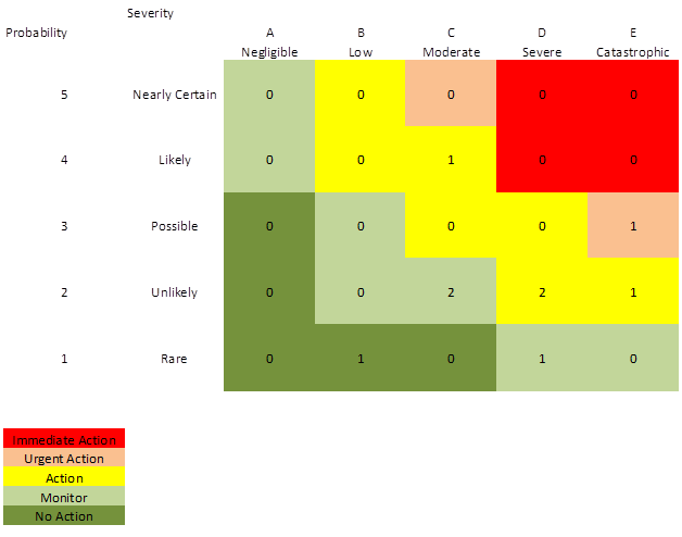
Figure 6 – Risk Overview
System Modeling
We’ve also been using a version of System Modeling Language in the Department of Defense Architecture Framework method to track our project’s interface, subsystem, and work breakdown requirements. By phrasing our system in terms of its activities rather than physical or functional breakdown, we see what the system does and what actions it needs to take to complete those high level capabilities. The highest level are the capabilities we intend to prove during validation (OV-1), and each layer beneath are activities that support that (OV-2(a-d) ), until a physical layer is reached. These are supported by our data containers (DIV-2), which represent the data passing between each activity.
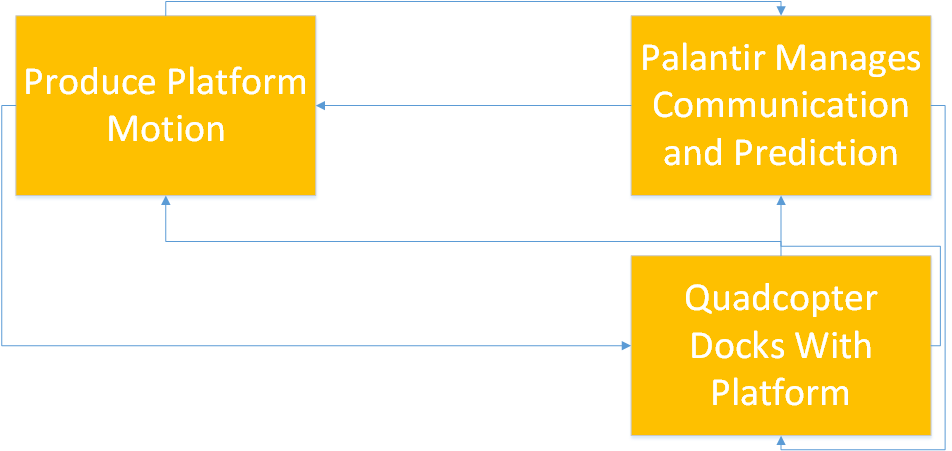
Figure 7 – OV-1 (High Level Capabilities)
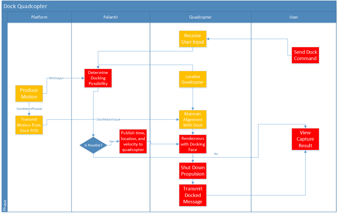
Figure 8 – OV-2 (Dock Quadcopter Activity Diagram)
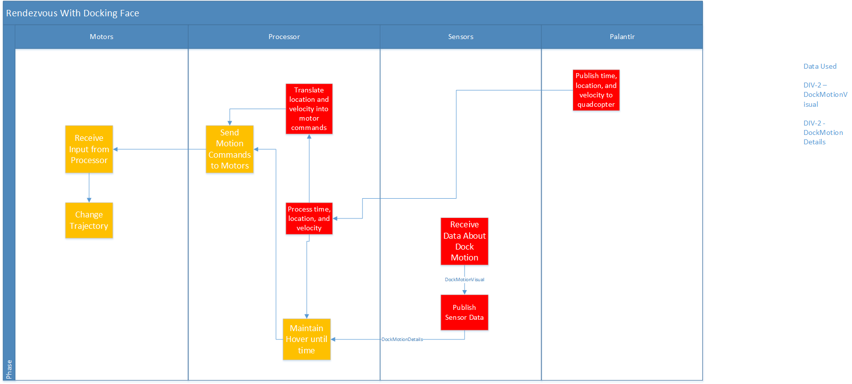
Figure 9 – OV-2b (Rendezvous with Docking Face)
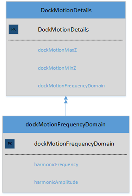
Figure 10- DIV-2 (Dock Motion Details Container)