There are five major subsystems in our project. These five subsystems are:
- The Integrated System
- The Obstacle Avoidance Subsystem
- The Vision Subsystem
- The Flight Control Subsystem
- The Ground Platform Subsystem
- The Electro-Mechanical Subsystem
Please visit the respective links to see the progress of each subsystem.
Integrated System
April 20, 2016
Finished integration of the system. Here is the link of the final demo video demonstrating the functionality of the integrated system – link
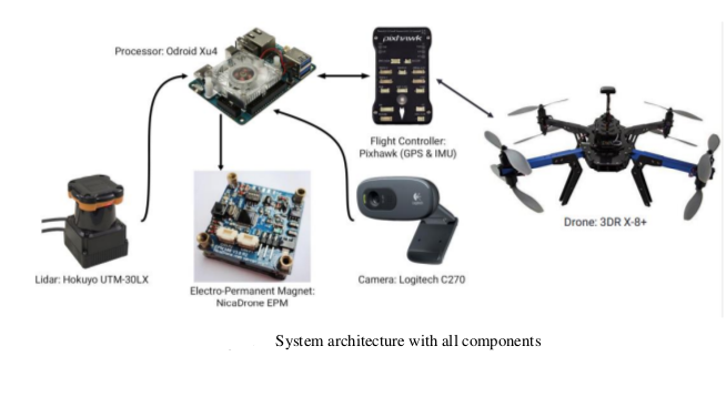
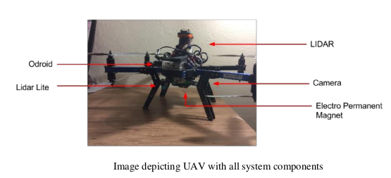
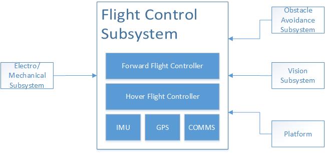
The overall system architecture and the UAV with all the components attached are shown below
April 13, 2016
Changes in obstacle avoidance system
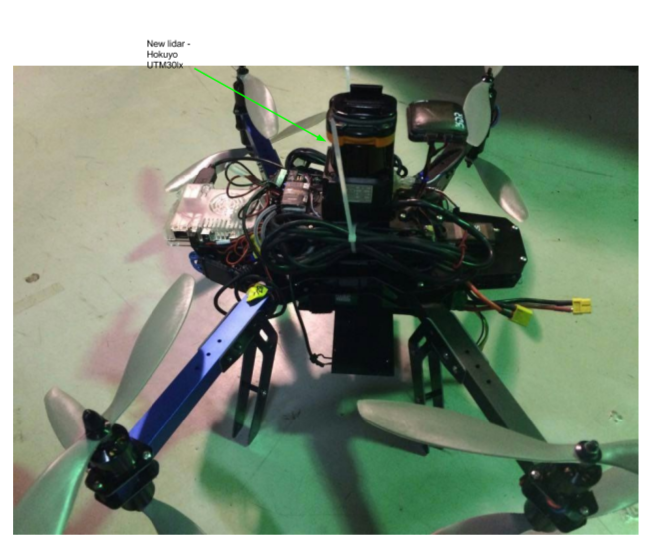
We discovered our obstacle avoidance sensor Hokuyo URG-04lx generates noisy data in outdoor environment. Hence we implemented the following solutions:
- Replacing our current sensor (Hokuyo URG04lx) with better outdoor sensor – Hokuyo UTM30lx
- Filtering the lidar data – we implemented median filter to get rid of any noise generated by the Hokuyo UTM30lx sensor
- Solving the Navigation stack raytracing issue – We observed that even though the lidar sees less noisy data after filtering the costmap remembers all the noisy data as obstacles and does not clear them later. We solved this issue by understanding and implementing the raytrace feature which clears the costmap based on lidar data.
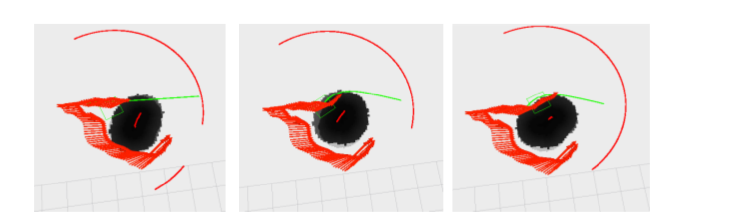
The above figure shows the rviz visualization of the UAV avoiding obstacles after replacing the sensor and applying the solutions mentioned above
March 31, 2016
Package delivery without obstacles
The UAV is able to deliver packages using the Electro-Permanent Magnet. The package upto 100g can be delivered to within 2m distance from the marker.
In the video above, the UAV takes off from starting point, ascends to 15m height, and goes to the pre-defined house position. Then, the UAV searches for the marker using a lawnmower search pattern. Once the marker is found, the UAV descends onto the marker, lands, and drops the package.
Lawn Mover search implementation with obstacle avoidance
We have achieved the functionality of the UAV traversing over a lawn mover search path to find the marker while avoiding obstacles. We flew the UAV at around 15m height the UAV followed the lawn mover path well. As we don’t have obstacles that high we could not verify the obstacle avoidance subsystem at that height. Next we will test obstacle avoidance using the test obstacles that we build for our project.
Physical Obstacle Design and Fabrication
The test requirements for the drone required that our project required the obstacles to be 1.5 x .5 m and 2 x 2 m. Upon further discussion as a team, we determined that two obstacles of 1.5 x .5 m would be more financially responsible in addition to raising the standards of the project as smaller objects are harder to detect.
The original design for the obstacles required that these profiles be elevated two stories in the air (approximately 6 meters). I planned to implement these using a scaffolding of ¾” PVC pipe. Tarp would cover the scaffolding to provide a surface for the Hokuyo Lidar to detect.
![Snapchat-5551699698106715790[1]](http://mrsdprojects.ri.cmu.edu/2015teama/wp-content/uploads/sites/2/2015/12/Snapchat-55516996981067157901.jpg)
Original Obstacle Design
However, upon inspection the ¾” PVC pipe was too thin to support the structure and would possibly buckle in the wind. 1-½” PVC would suffice but would also double the price. The team settled on a second design that was significantly less costly. The second design which is shown below.
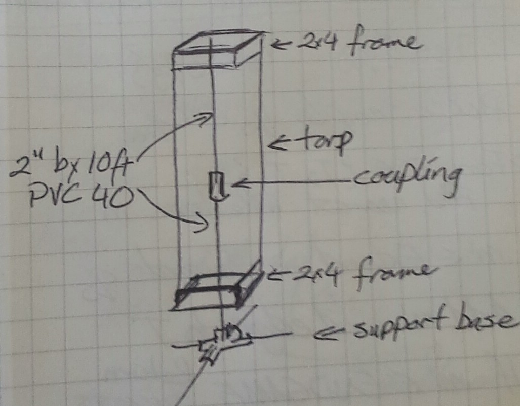
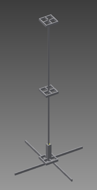
Updated Obstacle Design
The new design is significantly cheaper and easier to transport. It uses two 2” PVC for a support shaft. Tarp mounted to a 2×4 wood frame provides the body of the obstacle. The body will be hoisted into place by rope like a flagpole.
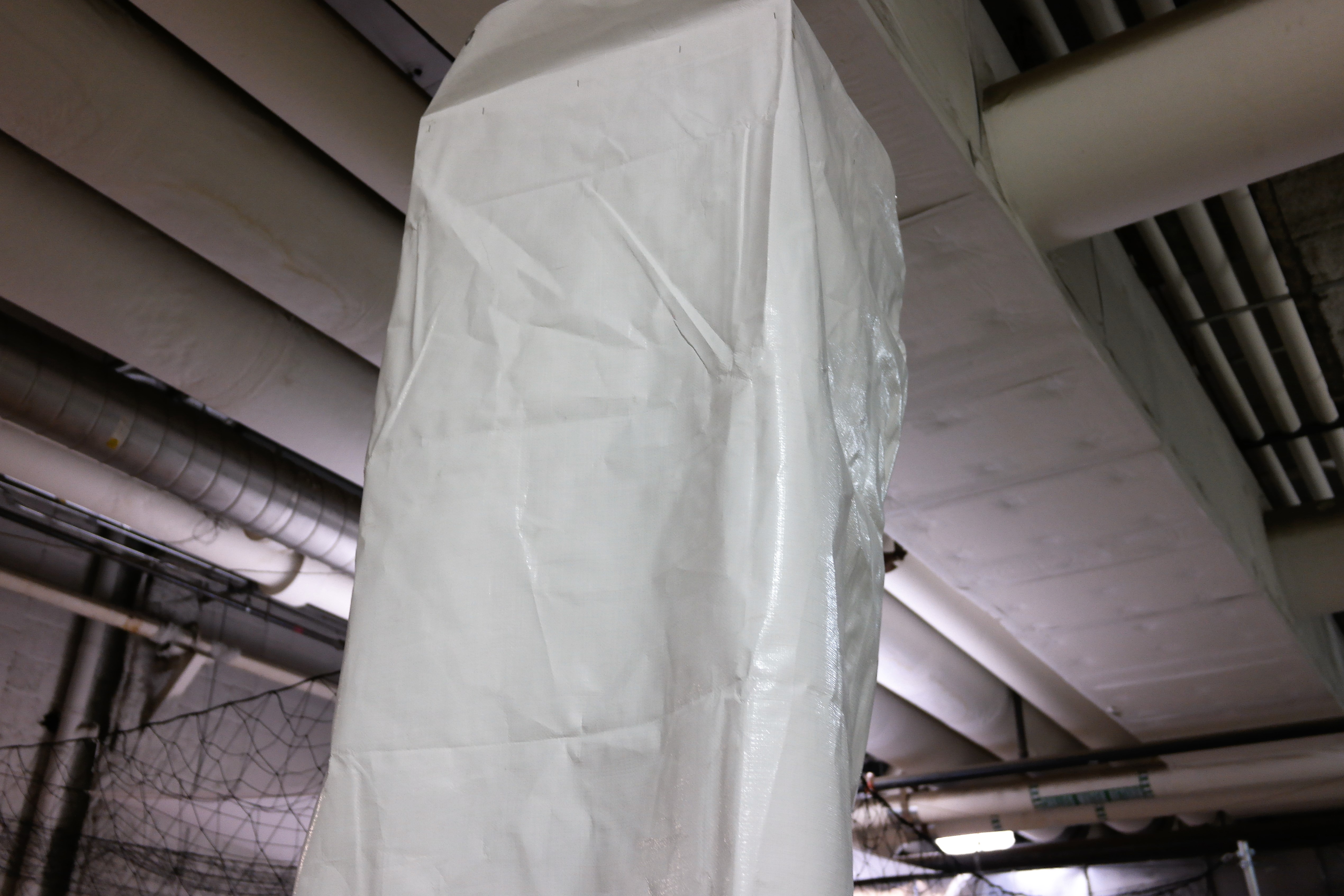
Tarp over wooden frame
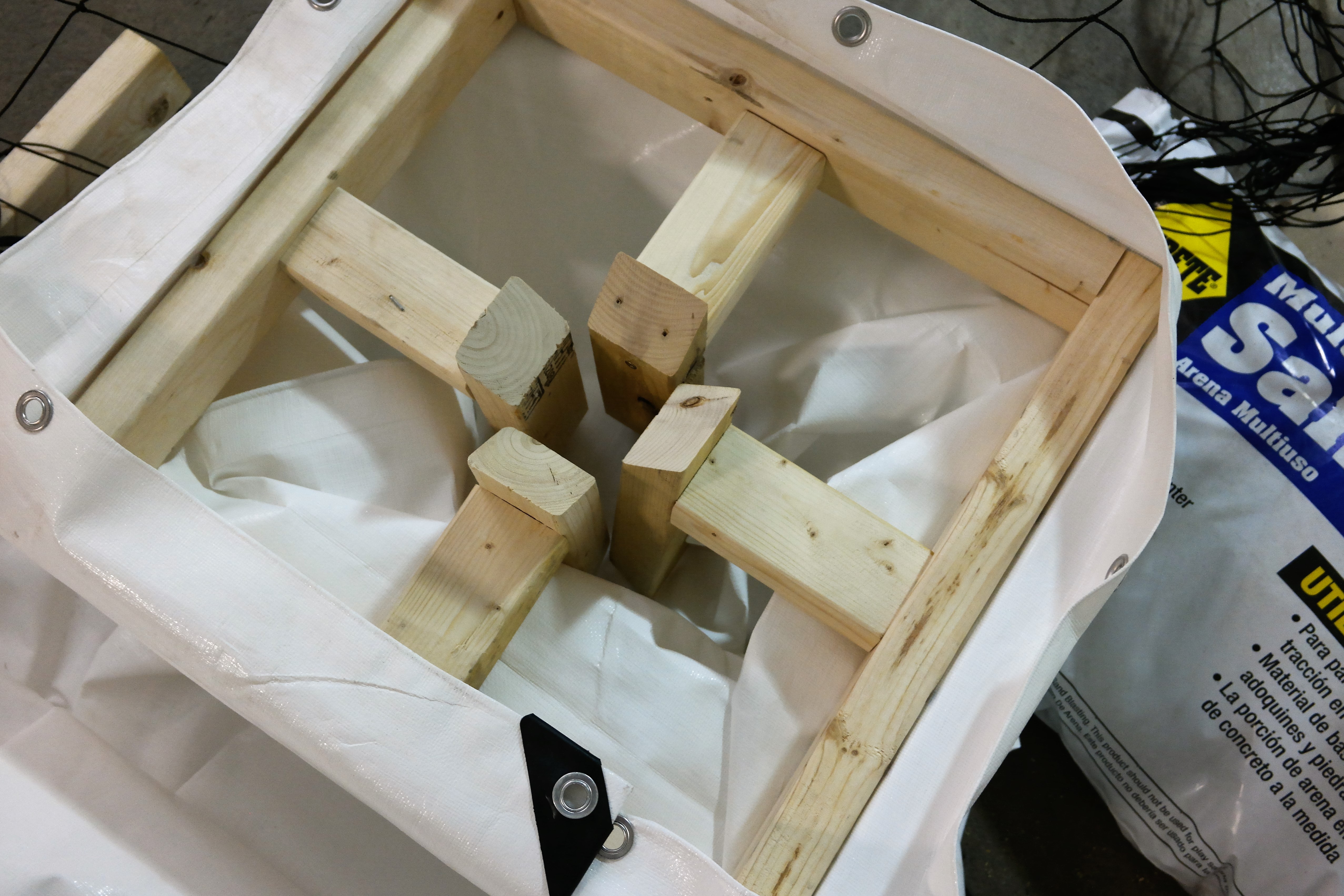
Close-up of Frame with Tarp Attached
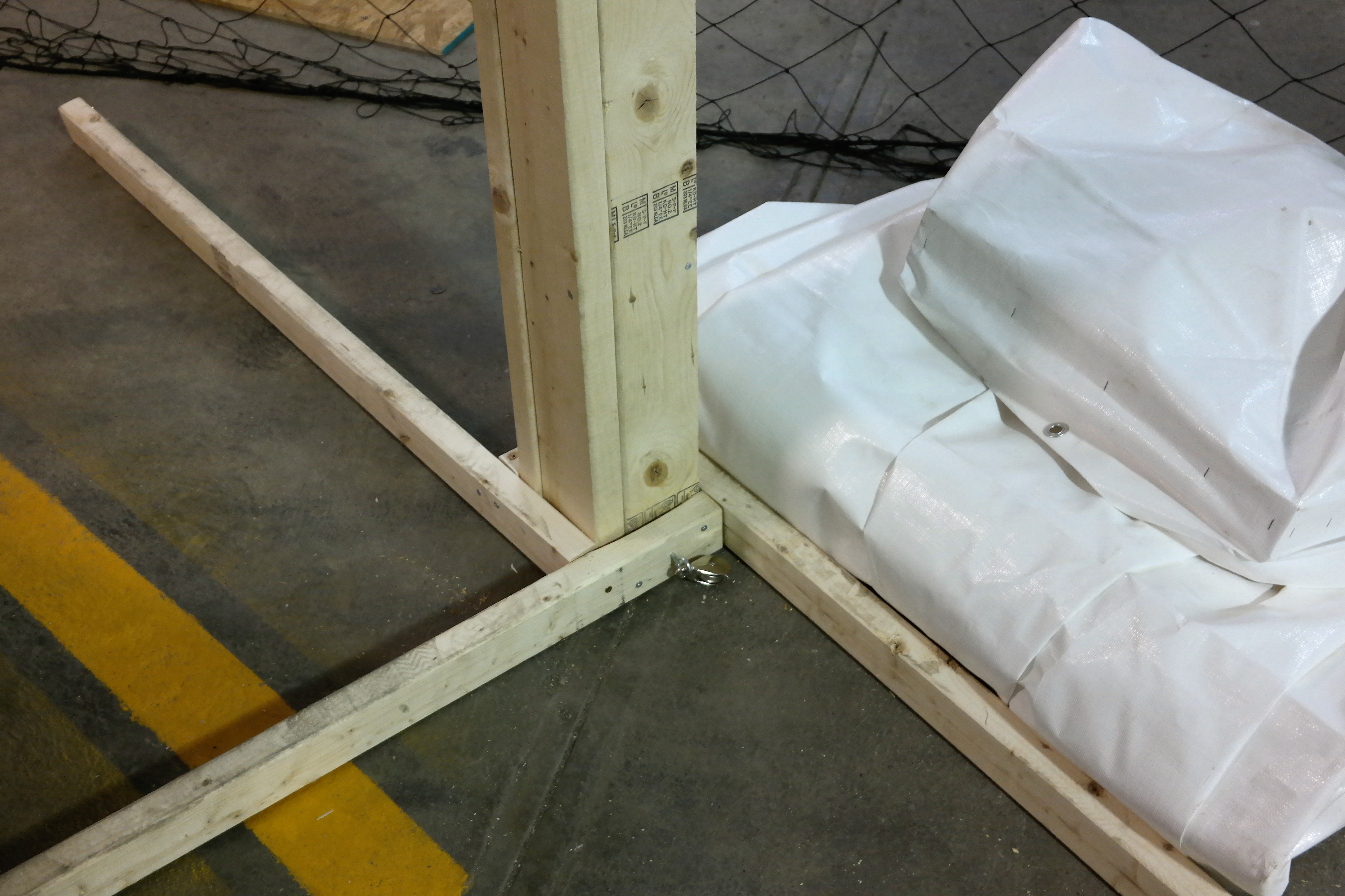
Obstacle Base
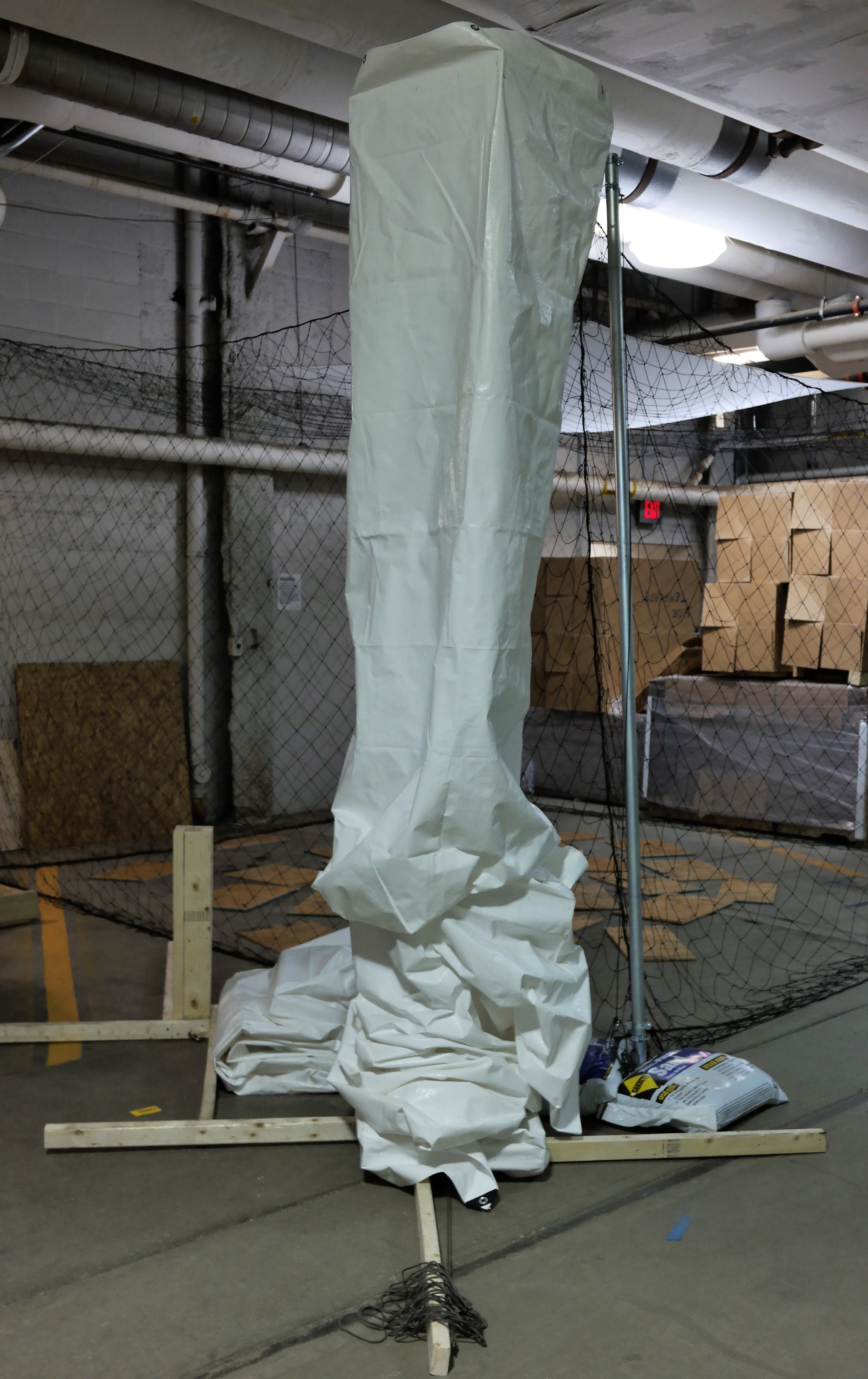
Obstacle partially erected to 10ft due to space limitations in lab
Fabrication of the final design took two days. We identified several improvements during the build that were incorporated into the final design. The hardest part of the build was the wooden frames for the tarp. Braces extend from all four sides to buttress the pole and prevent movement.
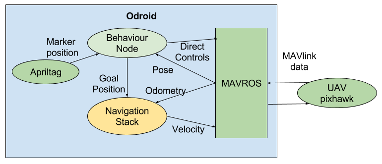
Updated Software Architecture
Manual RC control of Electro Permanent Magnet
March 17, 2016
Finishing Obstacle Avoidance code integration with Pixhawk- Running Obstacle Avoidance code off Odroid
Above shown is a video of the UAV performing autonomous navigation to the goal position while avoiding obstacles. The UAV can detect an obstacle from a distance of 3m and it maintains a distance of 0.5m from the obstacle at all time.
Autonomous Takeoff and Landing
In the above video, autonomous takeoff and landing functionality is demonstrated.
February 25, 2016
Primary integration of obstacle avoidance code with Pixhawk flight control code
We have achieved communication between Navigation Stack and the Pixhawk. After testing the code in Software In Loop Simulation of Pixhawk (as mentioned in Obstacle Avoidance Subsystem) we tested the code functioning on X8+.
Integrating Navigation Stack obstacle avoidance code with Pixhawk code
The output of odometry and navigation stack changed as we moved the UAV around manually. This verified that the Navigation Stack and the Pixhawk are communicating as needed.
February 10, 2016
Autonomous Navigation from A to B using Guided mode
The UAV takes off using manual RC control, then, the mode is switched for autonomous navigation. The UAV stays at the original point for 2 seconds and then moves ahead (UAV X axis) by 4m, and increases its altitude by 1m. It then holds its position until mode is switched back and the UAV is manually landed.
Autonomous Hover over Marker
As can be seen in the video, after the UAV is put into autonomous mode (audible beep), the UAV positions itself over the marker and maintains position at 18m height until its taken back to manual mode and landed.
The nested AprilTag marker is detected from the UAV and its target position is updated continuously to maintain position over the marker
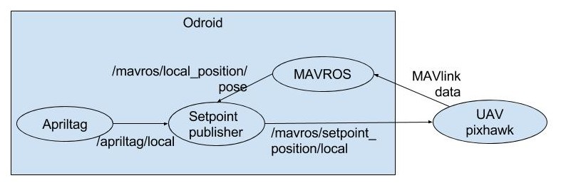
ROS architecture for autonomous hover over marker of the UAV. An apriltag detection node publishes the position of marker with respect to UAV. A setpoint publisher uses that and position data of the UAV to publish setpoints in global frame. (Takeoff point is origin)
The Obstacle Avoidance Subsystem
April 20, 2016
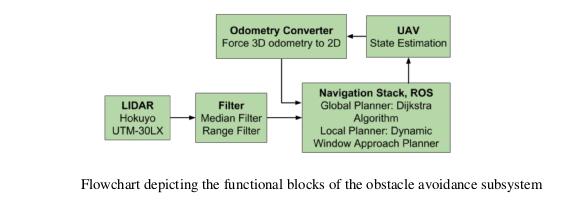
After February end we started integrating obstacle avoidance subsystem with the complete system. The details about the integration are mentioned in the integration section. The flow chart shown below describes the final logic that was used for obstacle avoidance
February 25, 2016
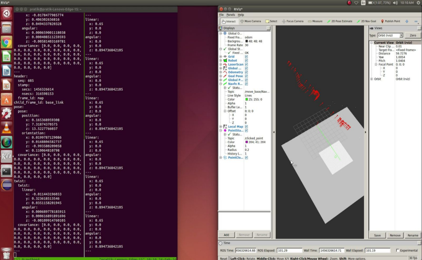
Testing Navigation Stack functionality with Software In The Loop Simulation of the Pixhawk. We could pass odometry data from UAV to navigation stack. Receiving this data the navigation stack passed velocity commands to UAV to move towards goal.
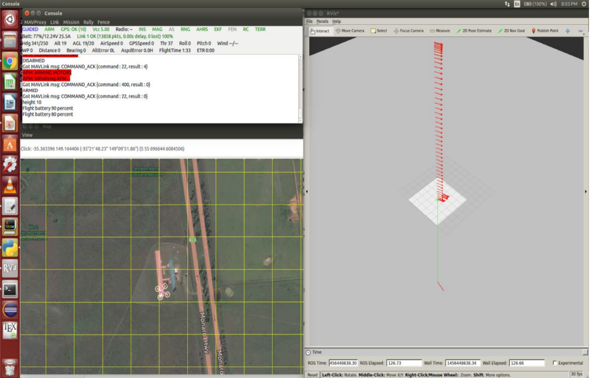
In the above figure, the tab on the upper left is the console which shows the data about the status of the UAV (its altitude etc.). The bottom left figure is the SITL map showing the virtual UAV in a virtual map. On the right is the rviz visualization of the UAV. The red arrow are the location of UAV. As seen in the figure the continuous vertical red line shows the UAVs takeoff. The green line is the path generated by navigation stack to reach the goal position (shown by a single sed line on the surface).
February 10, 2016
In simulation got the robot to follow the path planned by the planner.
Here is a video showing lawn-mover search implemented in simulation.
January 28 2016
We redid the trade study for Obstacle Avoidance Subsystem sensors as we shift to X8+ UAV platform. Now we are going to use LIDAR for obstacle avoidance sub-system. We are using Navigation Stack of Robotic Operating System for implementing obstacle avoidance.
The navigation stack contains the following parts:
Global costmap
Global path planner – It uses the global costmap to compute paths ignoring the kinematic and dynamic vehicle constraints. It uses Dijkstra’s algorithm to do this.
Local costmap
Local path planner – It accounts for the kinematic and dynamic vehicle constraints and generates feasible local trajectories in real time while avoiding obstacles
Move_base – It implements the state machine
Video below shows basic test of LIDAR interfaced with Navigation Stack of Robotic Operating System
We are using LIDAR instead of using 14 ultrasonic sensors because of the major reasons:
- As there are no aero-dynamic issue mounting LIDAR on X8+ for our system requirements we can substitute one LIDAR for 14 Ultrasonic sensors. Processing data from 14 sensors can be error prone and difficult to debug. LIDAR helps us get rid of this completely
- Data from ultrasonic sensors isnt consistent. Out of 14 sensors 2-3 sensors randomly give erroneous reading.
December 18 2015
The video below shows the functioning of 6 ultrasonic sensors mounted on the nose of the FireFly6 UAV
December 7, 2015 – Fall Validation Experiment
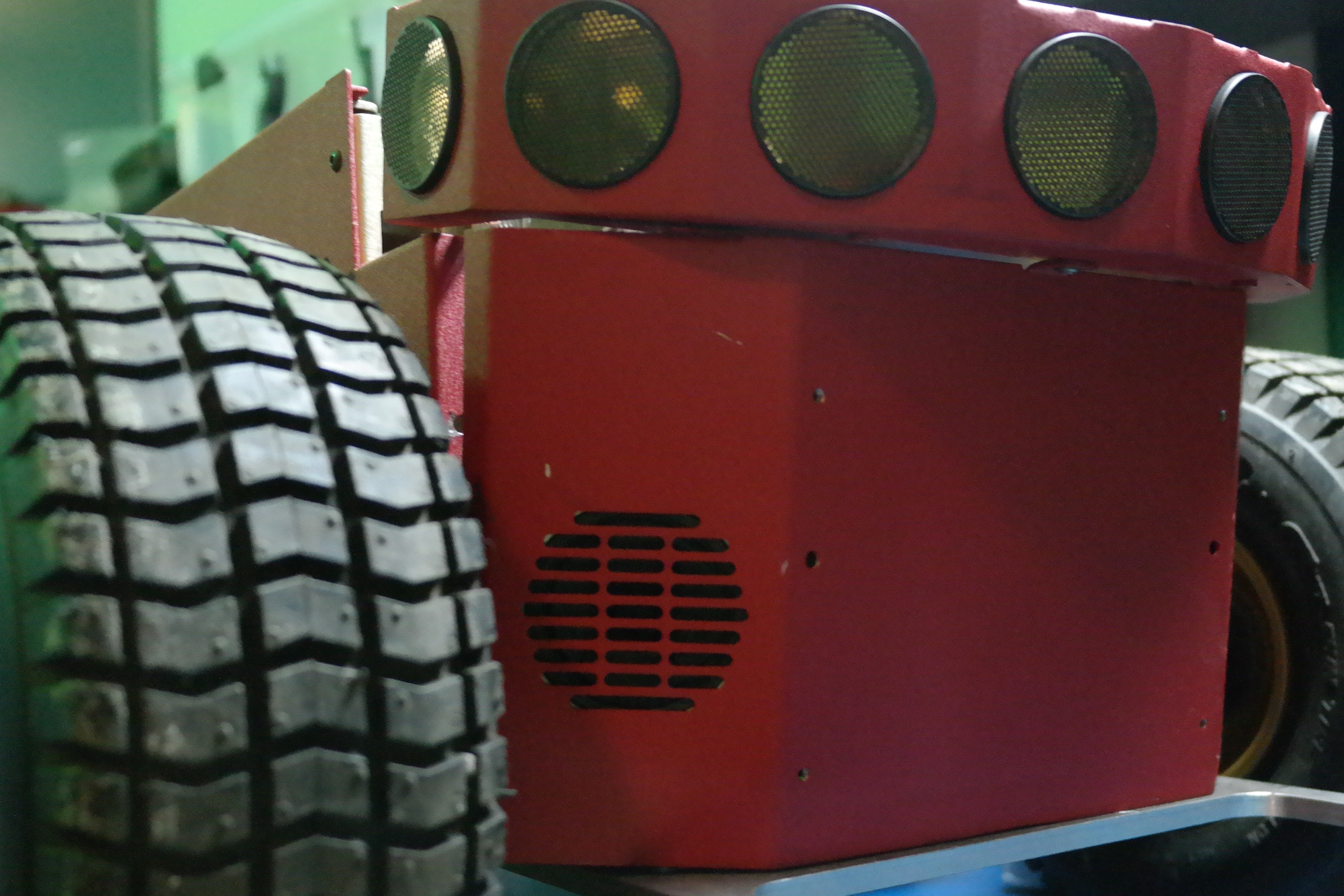
Figure below shows the 6 ultrasonic sensors mounted on the UAV.
Close Up of 6 Ultrasonic Sensors Mounted at the Nose of UAV
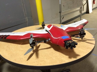
Image Showing 6 Ultrasonic Sensors Mounted at the Nose of the UAV
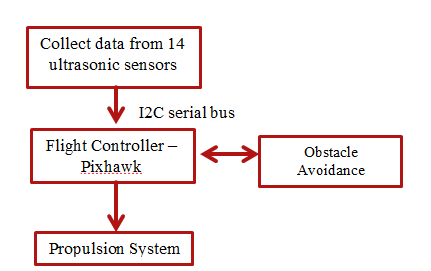
Flowchart of our obstacle avoidance system
Master-Slave Sensor Boards
As mentioned in the flowchart above we are using I2C communication for connecting 14 ultrasonic sensors to the flight controller. Hence we designed master board to handle combining of I2C lines and 5V regulator. Slave boards were designed to take sensor inputs and reduce analog line noise by converting it straight to digital.
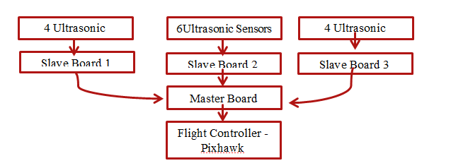
Flowchart of connection of sensors with the master-slave board
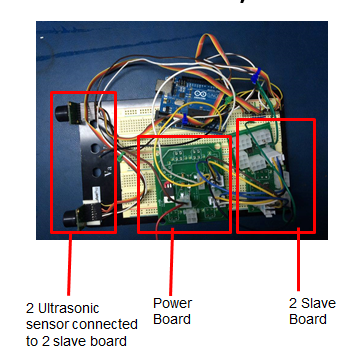
Fall validation master-slave test setup
November 07, 2015
CAD model of ultrasonic sensor layout on UAV
UAV with 14 ultrasonic sensor around it
Top view of sensor layout
Front view of sensor layout
The ultrasonic sensors are to be pinged serially to avoid interference among sensors. Each sensor takes around 50ms. So pining 14 sensors one after the other will take 50 X 14 ms = 700ms which is too much. SO we further divided sensors into 3 groups as shown below.
Subdividing the sensors into 3 subsystems to reduce uodate rate of iverall obstacle detection system
Master-Slave Sensor Boards
We are designing master-slave I2C board to connect all the sensors to the flight controller
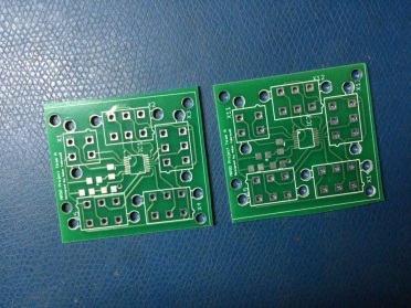
Two Printed Slave Boards
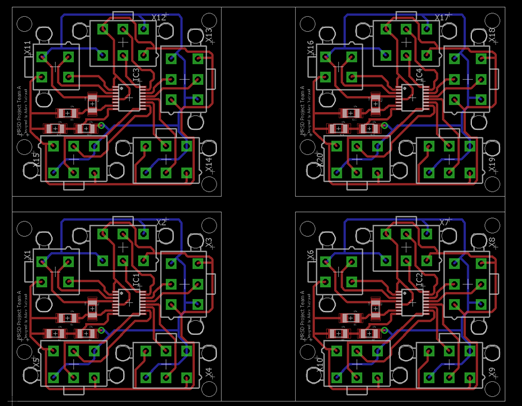
Schematic of 4 slave boards
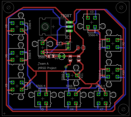
Schematic of the Master Board
October 30, 2015
Following are the tasks accomplished until now:
- Testing the sensors to detect trees, grass and obstacles that aren’t exactly perpendicular to the sensors
| Maxbotix EZ MB 1010 ultrasonic sensor | Maxbotix EZ MB 1040 ultrasonic sensor | IR sensor | |
| Detect trees | Yes | No | Yes |
| Detect grass | Yes | No | Yes |
| Can detect oblique obstacles (obstacles that are at an angle to sensor) | Yes | No | Yes |
| Oblique angle – angle at which if the sensor if tilted with respect to the obstacle then the obstacle won’t be detected | N.A. | 25-30 degree | N.A. |
- First iteration of obstacle avoidance system using IR sensors
From the tests with IR sensor we found out that the IR sensors have no cone and can be assumed to be detecting along a straight line. Doing the calculation we found out that we would require 39 IR sensors to detect the whole volume of 1.5 m around the UAV. As 39 was a huge number this would not work and we had to think of other option.
- Trade Study for selecting the sensor
| Sensor | Analysis |
| IR | For our system requirement we need 39 IR sensors to cover the whole area.
Too many sensors. |
| Lidar | Can detect only in one plane.
3D Lidar are too costly Mounting lidar on servo and rotating introduces more complexity |
| Ultrasonic | Cheap sensors Wide beam width Will require less ultrasonic sensors to cover whole area around UAV |
- Sequential pinging pattern for the Maxbotix ultrasonic EZ MB 1010 sensors to avoid interference
Maxbotix has provided with an arrangement on the sensors to sequentially fire the sensors.
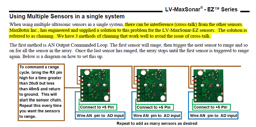
Sequential firing of ultrasonic sensors as per LV MAxbotix EZ MB 1010 datasheet
October 23, 2015
Developed obstacle avoidance sensor system of two IR and two ultrasonic sensors on UAV model that Sean built so that we can perform various tests indoors as well as outdoors. We then did conduct range test with the sensors.
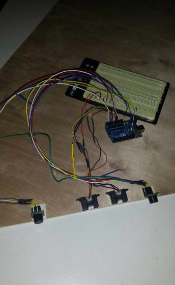
Sensor Setup of 2 Sharp IR GP2Y0A02 IR sensors and 2 Maxbotix LV Maxsonar EZ ultrasonic sensor
October 16, 2015
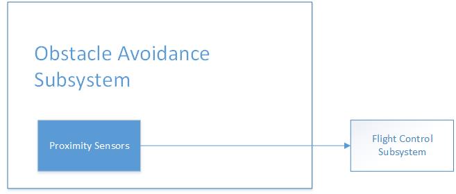
Obstacle Avoidance Subsystem
This subsystem is comprised of the sensors necessary to detect objects in the UAV’s path. As described in the system trades section, selecting sensors is still under way. We have analyzed many different options such as LIDAR, IR, ultrasonic, and more, but some of the tradeoffs between weight and price are still undecided. We are aware of our constraints, but the relevant weights of the constraints is dependent on the success of our electro permanent magnet system as well as the weight and location of our cameras. This will be decided within a week of receiving and testing the gripper.
Current Status
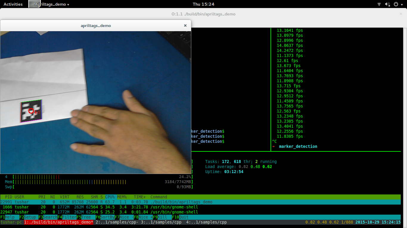
The vision system has been developed to run using a Logitech webcam on an Odroid. We use nested AprilTag markers and AprilTag detection coupled with Lucas Kanade tracking algorithm to track the marker location. It is able to achieve upto 29 frames per second update rate and can detect the marker upto 20m.
December 7 – Fall Validation Experiment
To increase the speed of the detection of the marker (AprilTag) we used a combination of AprilTag detection and Lucas Kanade Tracking.
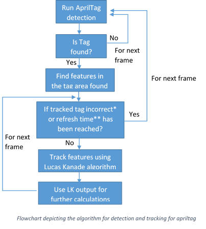
We use the AprilTag detection as the primary algorithm. After the first frame in which the tag is detected, the features were obtained from this frame and tracked in the following frames using the Lucas Kanade tracking. The output obtained from the tracking results was be verified for correctness*. In case no tag is obtained or the tag obtained is incorrect, we shifted back to the AprilTag detection for the next frame. As tracking results may start deviating from the actual detections, it is good idea to refresh the estimates using the AprilTag detection once every few frames**.
*correctness of the tag can be verified in multiple ways: (the basic version was tested to be a good enough measure of correctness)
- Basic: verify that the tracked points form a sensible quadrilateral.
- Advanced: also include using the decoding logic of apriltags to verify the tag
**we used a refresh time (or number of frames) after which the full detection is run to refresh the tracking results. This is done as the tracking results can deviate due to errors and occlusions. A refresh every 30-60 frames gives a good output.
| Algorithm | FPS on Laptop
(i3 4th gen) |
FPS on Odroid
(Quad core ARM) |
| AprilTag detection | 14 | 8 |
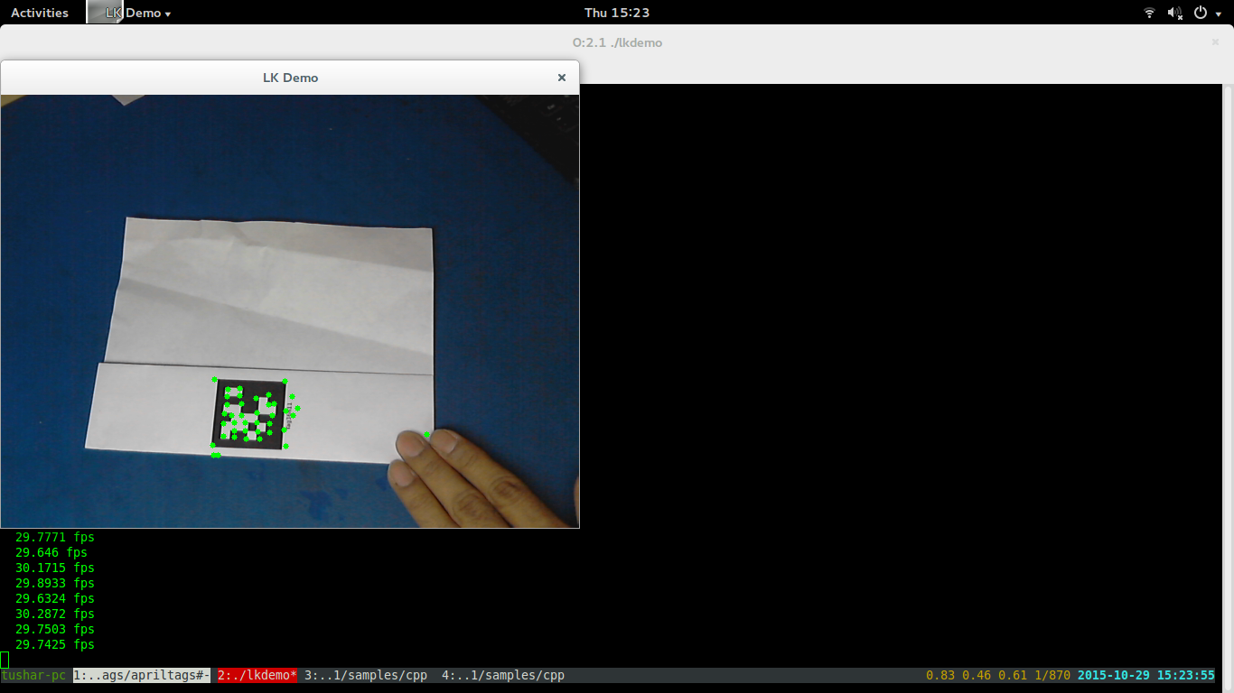
| Lucas Kanade Tracking | 30 | 29 |
| Merged
(LK + AprilTag detection) |
29 | 28 |
Comparison of speeds of detection between different algorithms
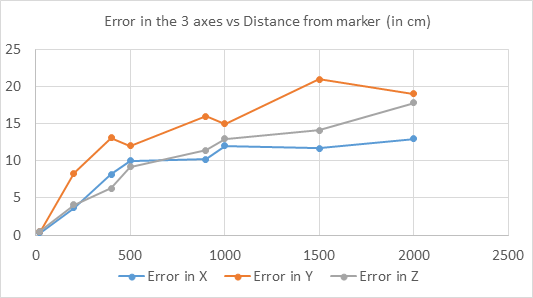
Error in the 3 axes vs Distance from marker (in cm). Less than 5% error found
November 13
Based on previous results we decided wo use the AprilTag detection system and speed it up using some workarounds.
Marker for detection – Nested AprilTags
To increase the range of detection of the marker, a nested AprilTag was developed.
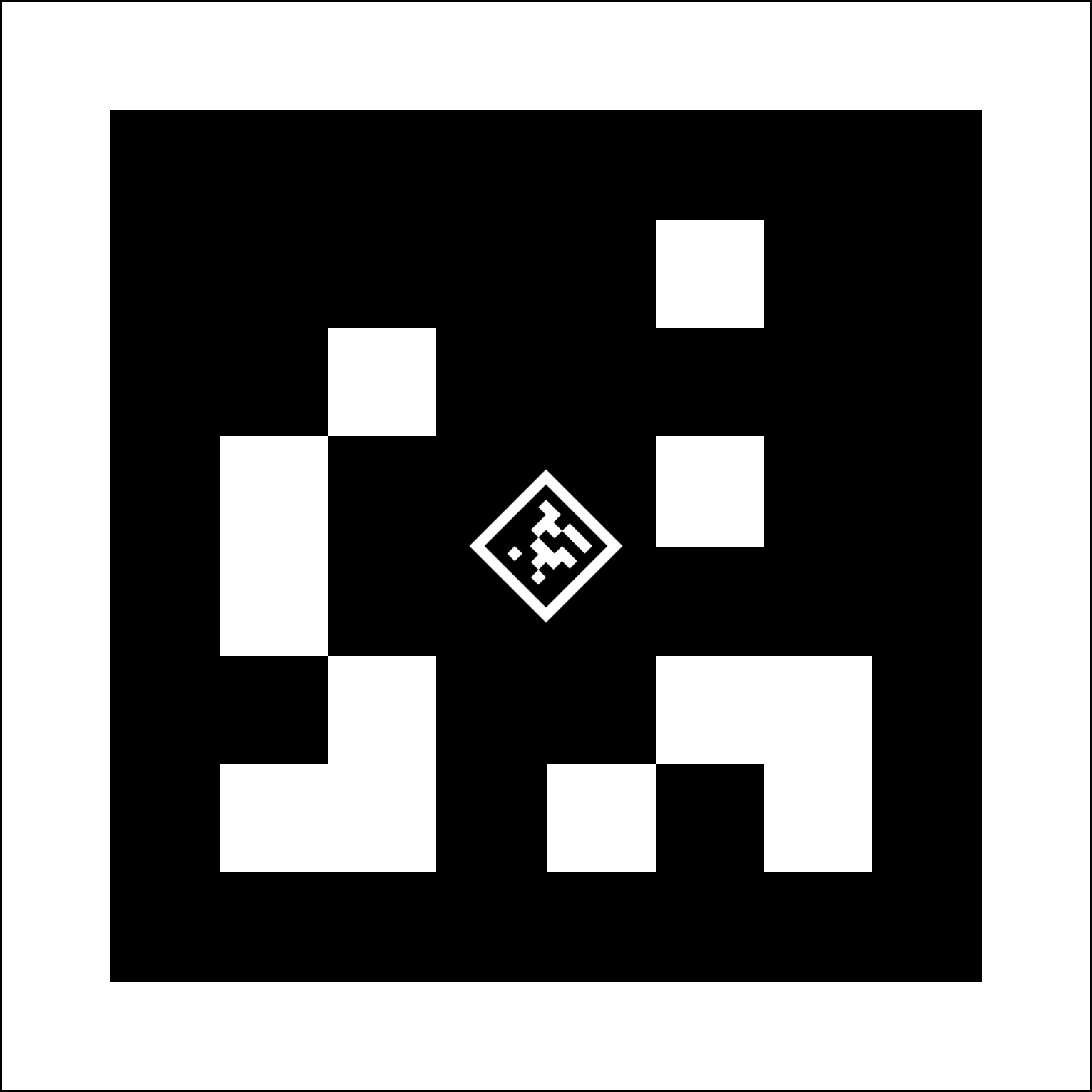
Nested AprilTag marker. Inner AprilTag is one tenth of the outer, and is rotated by 45 degrees counter-clockwise.
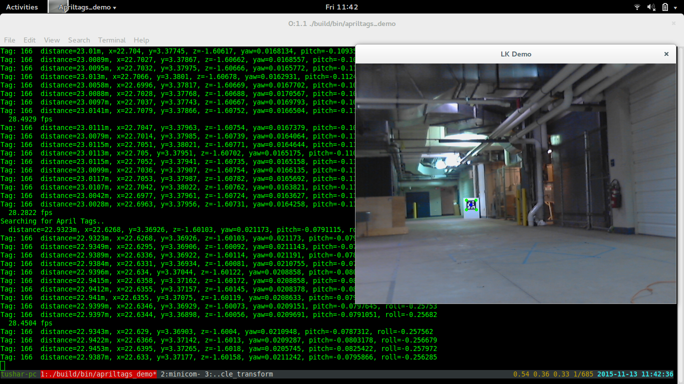
Nested AprilTag outer marker detection. Green Dots indicate corners of marker and blue marks the center. (Marker: Nested Apriltag, Distance: 22.938m, FPS: 28).
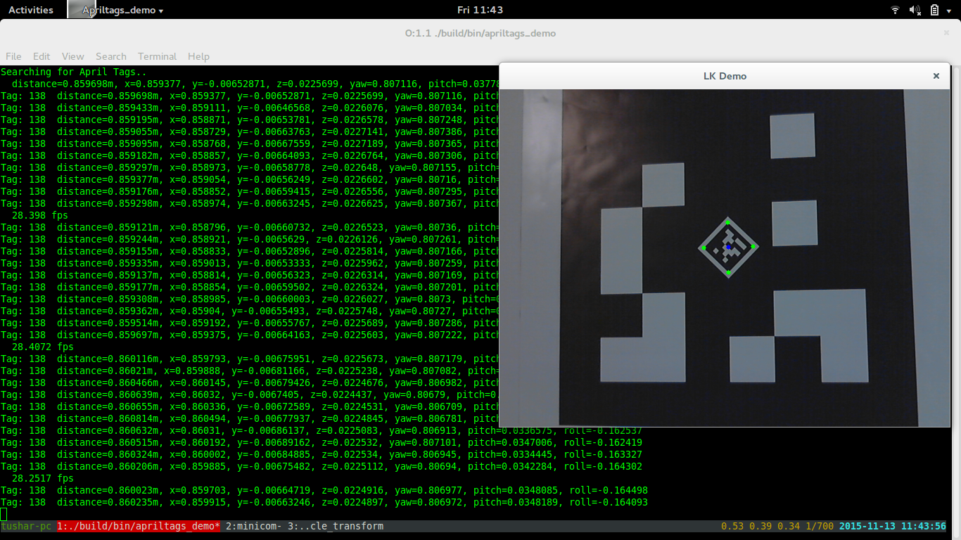
Nested AprilTag inner marker detection. Green Dots indicate corners of marker and blue marks the center. (Marker: Nested Apriltag, Distance: 0.86m, FPS: 28)
| S.No. | Detection distances for different nested apriltag markers | |||
| Outer AprilTag | Inner AprilTag | |||
| Size | Range | Size | Range | |
| 1 | 3.6cm | 8cm to 1.8m | 0.36cm | Not detected |
| 2 | 14.4cm | 40cm to 7.2m | 1.44cm | 4cm to 50cm |
| 3 | 57.5cm | 1.6m to 30m | 5.75cm | 16cm to 2m |
October 30
We switched to the Odroid XU4 as it has approximately 4 time sthe processing power and has 8 cores. Setup the Odroid XU4
- Ubuntu 14.04 server image
- ROS Indigo
- OpenCV
- Logitech C270 webcam drivers
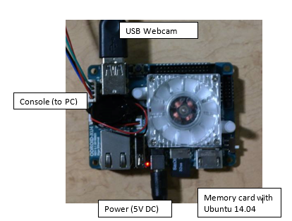
Odroid setup. Including peripherals and connections
Detection Algorithms
Few algorithms were tested and compared:
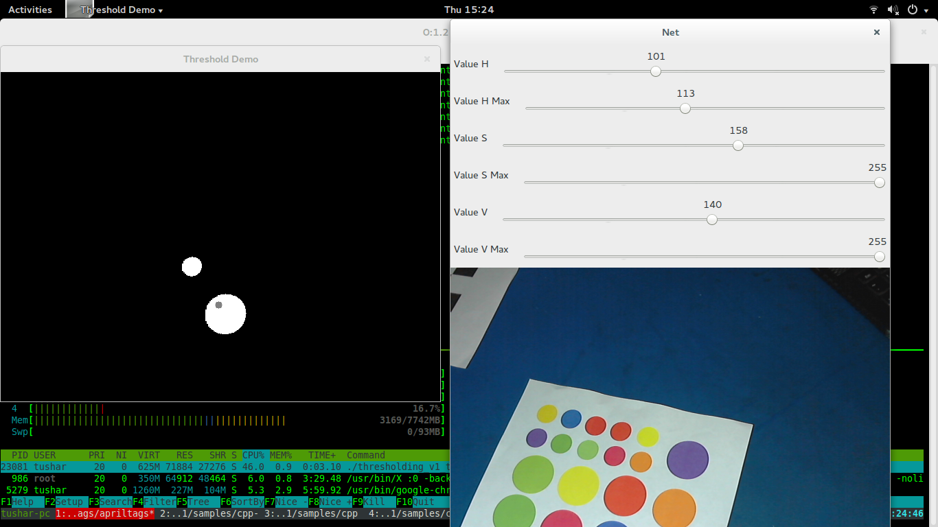
- Color thresholding and centroid calculation

Color thresholding and centroid results. Fast but not robust to lighting variations.
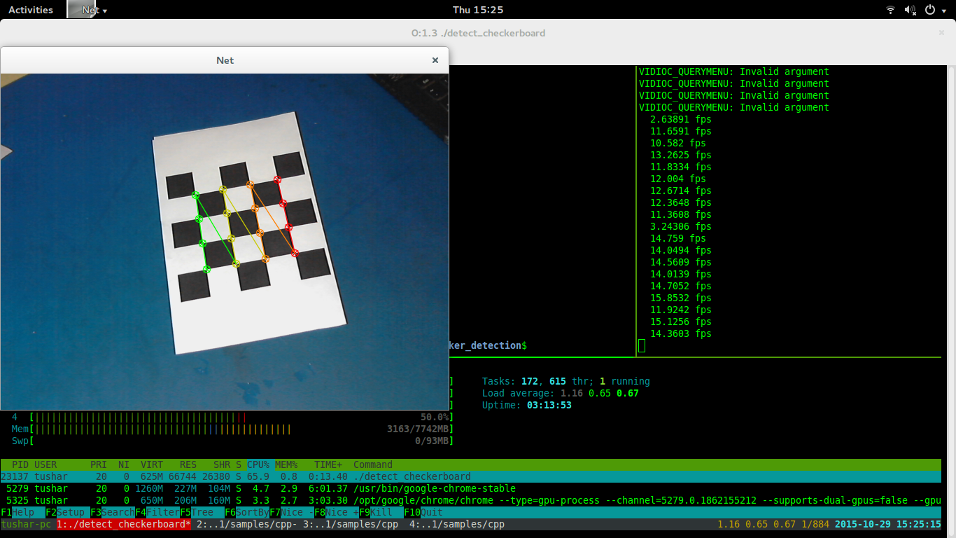
- Checkerboard pattern detection
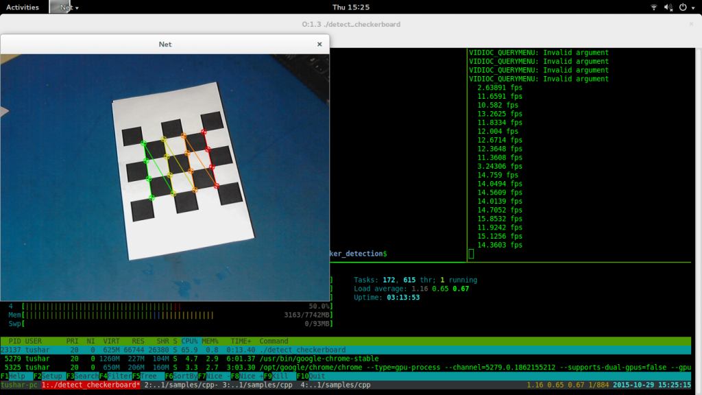
Checkerboard pattern detection. Not very fast but quite robust.
- AprilTag detection
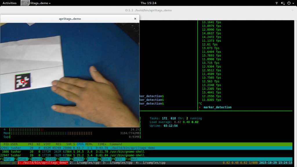
AprilTag detection. Not very fast but very robust.
- Lucas Kanade Tracking

Lucas Kanade tracking of AprilTag features. Fast and robust for small movements but needs an initial good detection.
Comparison of algorithms
| S.No. | Algorithm | Speed (frames per second processed) | Detection results |
| 1 | Color thresholding and centroid detection | 30 | Bad in lighting changes |
| 2 | Checkerboard Pattern | 14 | Slows down in bad lighting |
| 3 | AprilTag detection | 14 | Very robust to lighting and pose |
| 4 | Lucas Kanade Tracking | 30 | Very robust but requires a detection beforehand |
October 23
Setup the Beagleboard xM for the vision subsystem:
- Ubuntu 14.04 server image
- ROS Indigo
- OpenCV
- Logitech C270 webcam drivers
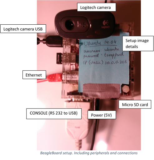
BeagleBoard setup. Including peripherals and connections
October 2, 2015
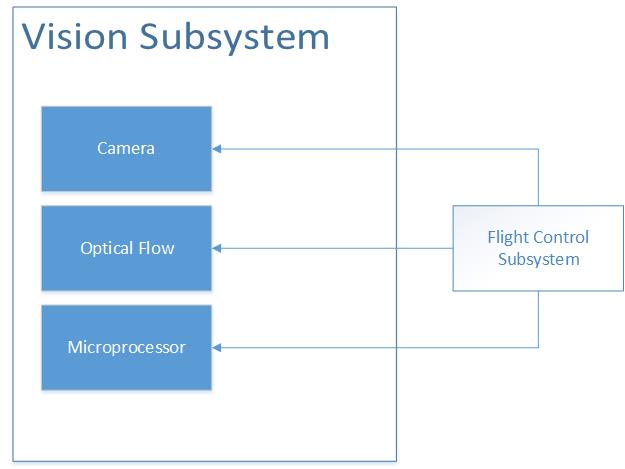
Vision System
The vision subsystem handles all the visual processing. It is the eyes of the UAV as well as a source of visual odometry. The vision subsystem contains a camera, an optical flow sensor, and a microprocessor. The microprocessor is the board that handles all the computer vision algorithms in real time. Based on trade studies, this board will be a BeagleBoard-xM or a Raspberry Pi 2. We plan to start with the BeagleBoard-xM because we have experience using them in previous projects and because it has higher processing power. Due to the fact that a Raspberry Pi 2 is cheap and well documented, though, we will also buy one of those as well as a backup.
January 28, 2016
We decided to switch our UAV platform after Adam, our flight control expert, dropped out. We are now using the 3DR X8+, a ready to fly UAV platform which uses the popular DroneCode stack.
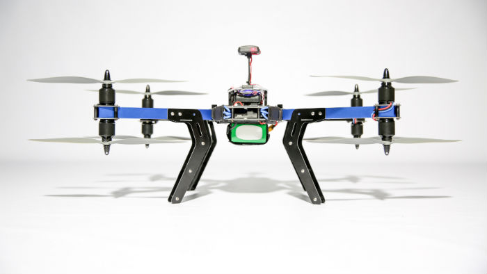
The UAV is set up and looks very promising for fast future development.
December 7, 2015 – Fall Validation Experiment
Our current status is that the vehicle is procured, assembled, and semi-functional. The electronics can be seen inside the vehicle in the figure
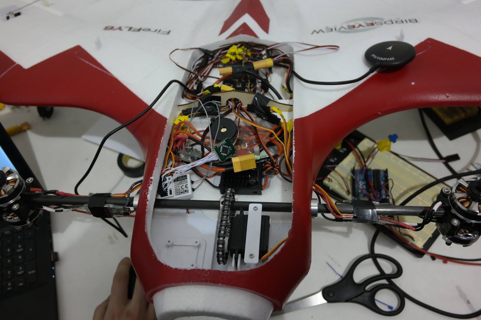
Electronics Installed in FireFLY6
October 2, 2015
Flight Control Subsystems
The flight control subsystem is arguably the most critical subsystem of the entire vehicle. It is the only system that interacts with all other subsystems and it involves the most interconnected components out of any of the subsystems.
Due to the fact that our vehicle is a fixed-wing VTOL vehicle (FireFly6), it requires two flight control boards to fly. The two boards handle different modes of flight, namely forward flight and hover control. An APM flight controller will be used for forward flight and a Pixhawk will be used for hover control. Both boards will be running Arducopter software and connect to the Bridge, which is an intermediate motor controller on the FireFly6. For simplicity of further explanations, both flight control boards will be referred to simply as the flight controller.
The flight controller must interact with all sensors on the UAV. Such sensors include the GPS, IMU, and the proximity sensors indirectly by way of the obstacle avoidance subsystem. The flight controller also has a radio plugged into it to communicate with the platform subsystem. The flight controller takes all this incoming data from all the various subsystems and transforms it into control outputs for the propulsion system.
Although the flight control system is the most critical subsystem of the entire vehicle, it is also the most well tested part of the vehicle. Part of our analysis in the systems trade included looking at the flight controller capabilities and firmware documentation. Arducopter software has been super well documented and used by many people. Pixhawk and APM flight controllers have also been well tested over the years. As a result, although this system is so critical and thus produces a central point of failure for the vehicle, it also is one of the most robust because of conscious effort to make sure it was well tested by others.
February 19, 2016
Due to losing a team member over winter break, the team rescoped the project away from using a ground vehicle platform in order to prioritize the core technology of the project.
December 7, 2015 – Fall Validation Experiment
We are using Pioneer 2 UGV as our ground vehicle platform. The Pioneer 2 that we received from the institute inventory want functional. We redid the electronics and mechanical part to get it working.
Pioneer 2 during Rebuild
October 2, 2015
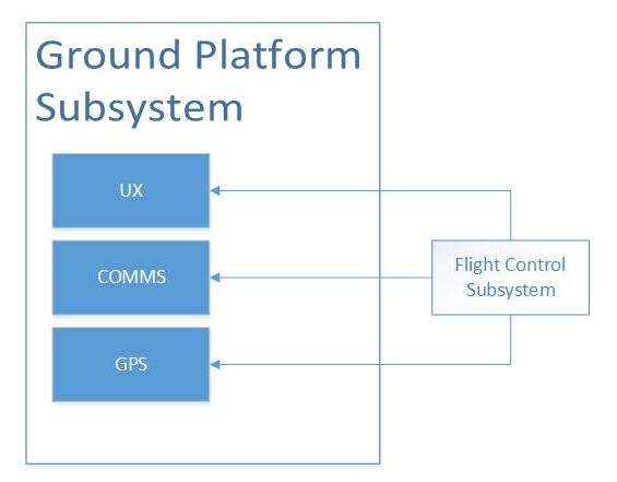
Ground Platform Subsystem
The platform subsystem is a simple mechanism that models the UGV. It is an intelligent platform that contains a GPS, user interface, and communication channel to the UAV. Its sole purposes are to allow human input into the system and to provide a takeoff and landing spot for the UAV. This platform will be useful for many stages of testing from the out-of-the-box tests all the way to the final system validation tests.
The Electro-Mechanical Subsystem
March
February 19, 2016
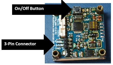
The NicaDrone “gripper” arrived before the stare of the semester. In order to continue with our project, we had to test the functionality and performance of the NicaDrone Electro Permanent Magnet. To complete the test, we connected the “gripper” to the DC power supply through the 3-pin connection on top. Only the 5v Source and Ground Terminals needed to be connected as controlling the on/off function can be controlled by the button on top. We will make use of the PWM Terminal via the Pixhawk in the future for electronic activation of the magnet.
Connecting a metal plate to the bottom of the gripper, then power it on, ensured resulted in a strong connection. The exact weight is unknown; however, it is several times the weight of any box we would want to attach to the drone.
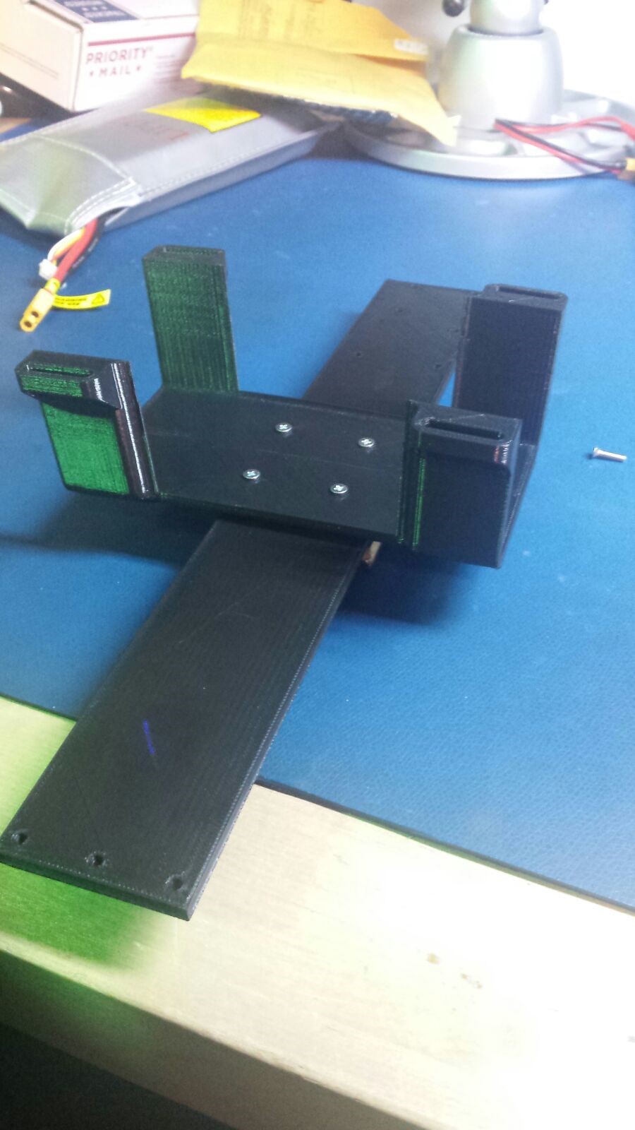
With the NicaDrone Electro-Permanent Magnet in hand, we were able to design and fabricate the first variation of the underbelly design. Design was done in phases. Starting with the base for the NicaDrone, we worked outward to the sides of the package. The current design attempts to balance the camera on one side with the PX4Flow and LidarLite on the other. This design minimizes the effect on the center of gravity, but still needs to be validated. The current design is modular, allowing us to more quickly tweak the individual components before moving toward a more elegant design.
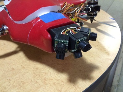
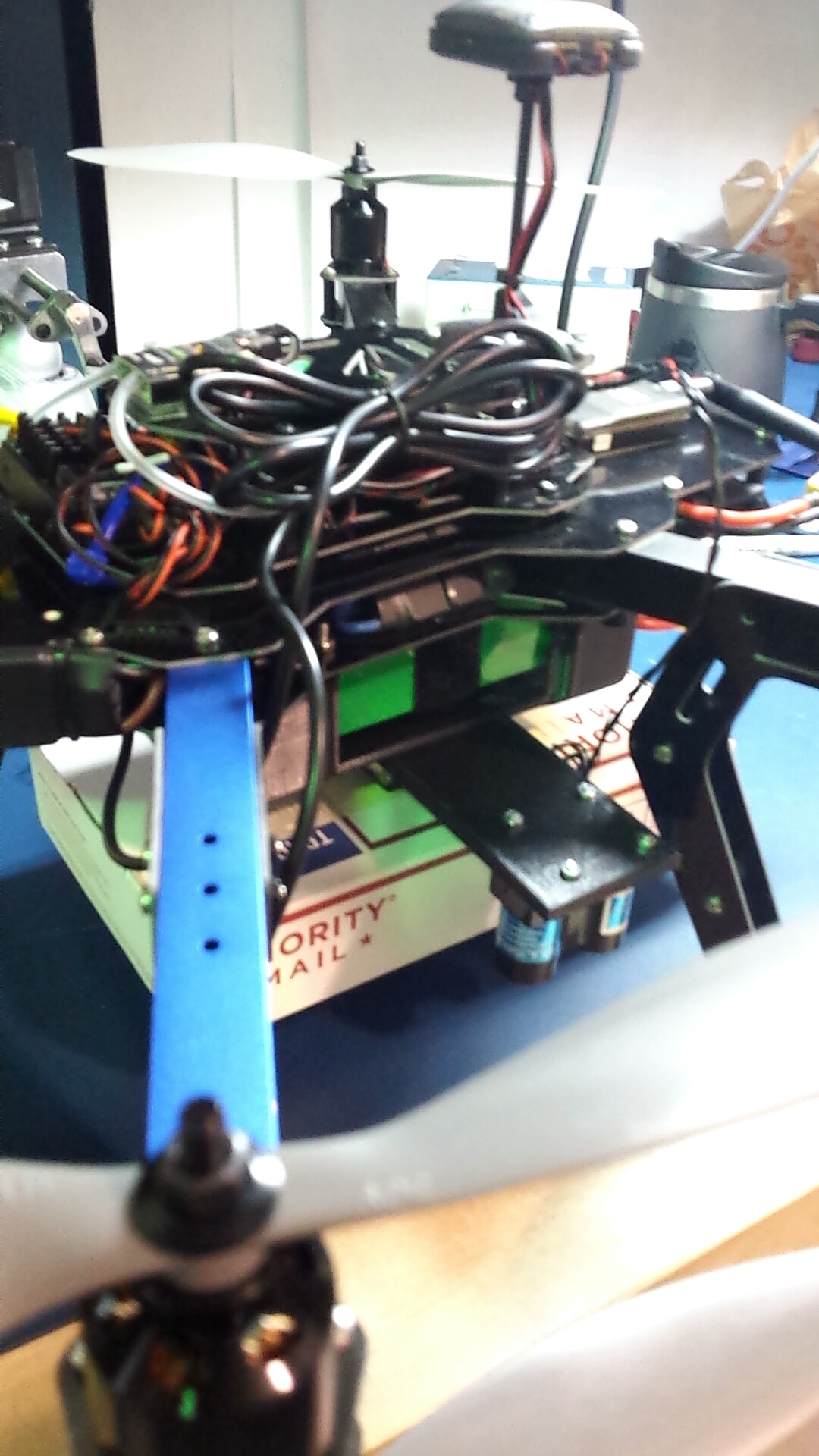
Here are two pictures of the fabricated underbelly. Note the NicaDrone attached to the bottom.
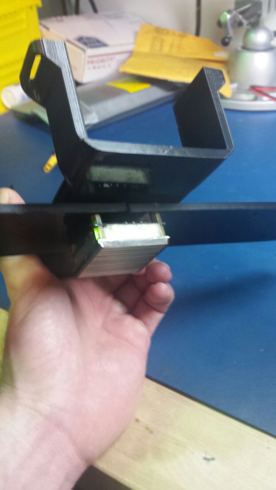
The next step was to attach the underbelly to the bottom of the 3DR x-8+. This was easily done thanks to mounting holes on the drone’s body.
This is what the drone looks like with the underbelly mounted and a package attached.
The final step was to modify standard USPS shipping packages to interface with the Electro-Permanent magnet. NicaDrone provided several small, magnetic plates along with our order. We settled on an approach (similar to that used for RFID tags) of implanting a magnet underneath an adhesive pad.
Details of this simple method can be seen here:
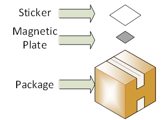
The approach was the most feasible for shipping companies to implement. It does need to be centered on the package, however it does not require special boxes or opening packages to insert a plate.
During testing, this method was able to hold 5 lbs of tension with the electro-permanent magnet. The package was released under its own weight in under a second. This approach worked best when the NicaDrone was physically touching the package. The only limitation was with the adhesive strength of the tape, which came off around 15 lbs, not the magnet.
December 7, 2015 – Fall Validation Experiment
Nica Drone – the electro-permanent magnet that we will be using for our system isn’t available for shipping at the moment. We will work on this front in spring semester.
October 2, 2015
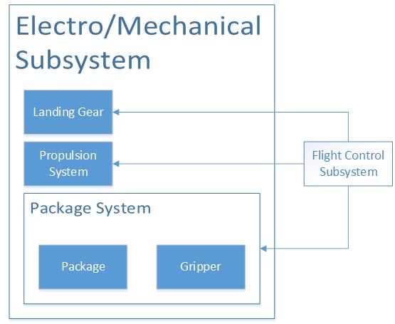
This is the part of the vehicle that involves moving parts. Specifically this system is composed of the propulsion system, landing gear, and package system. The landing gear is specific to our vehicle choice and is composed of actuated legs controlled by a servo. The propulsion system consists of the motor controller, the electronic speed controllers (ESCs), the motors, and the propellers. The propulsion system is responsible for converting electrical signals into thrust and flight.
The last major component of the electro-mechanical subsystem is the package system. This package system consists of the package itself and the gripper which handles the package. Currently our gripper is composed of an electro permanent magnet board that can lift up to 5kg and weighs 35g. Should this fail, we have designs for a mechanical gripper that we would design ourselves but the electro permanent magnet far exceeds all other design options and we will work hard to ensure it integrates with our system.