a. System requirements
Functional Requirements
- The system shall
- F1. Have two major components: quadcopter and moving docking platform
- F2. Detect and communicate when docking and undocking is not possible
- The docking platform shall
- MF1.1 Be moving until the quadcopter has been docked
- MF1.2 Withstand the weight of the quadcopter once it has been docked
- The quadcopter shall –
- F2.1 Localize itself w.r.t. the platform
- F2.2 (MOVED TO DESIREABLE)
- F2.3 Navigate to the platform
- F2.4 Dock to the platform without any collision
Non Functional Requirements
- The system shall:
- MNF1.1 Function in a GPS degraded environment
- MNF1.2 Provide a user interface with DOCK command and provide status
- The quadcopter shall:
- MF2.1 Have a payload capacity of > 500g
Performance Requirements
Mandatory Requirements
- The docking platform will-
- MP1.1. Have 1 degree of freedom along Z-direction
- MP1.2. Oscillate in harmonic motion with dominant frequency < 0.3Hz
- MP1.3. Have oscillations’ span ±200mm
- MP1.4. Have a locking mechanism which supports weight of 5kg
- The quadcopter will –
- MP2.1. Localize w.r.t. platform within ±50cm
- MP2.2. Navigate to the platform within 10 minutes
- MP2.3. Dock to the platform autonomously and without colliding within 10 minutes
Desirable Requirements
- The docking platform will-
- DP1.1. Have 3 degrees of freedom along X, Y and Z-direction
- DP1.2. Have random movements in 3D space
- The quadcopter will –
- DP2.1. Localize w.r.t. platform within 30cm accuracy
- DP2.2. Navigate to the platform within 5 minutes
- DP2.3 Plan a path to the docking platform
b. Functional architecture
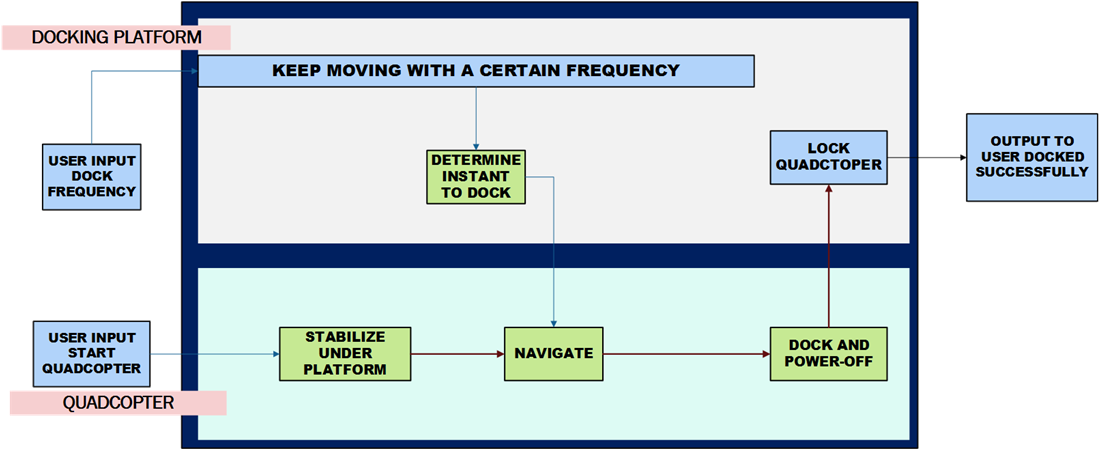
Figure 1 – Functional Architecture of the Docking mechanism
The system’s input is the user’s decision to dock and the output is the successful dock. The architecture is divided into two parts – the quadcopter and the platform. The quadcopter and platform are working together to plan the approach to the docking platform and dock at an opportune moment. There are three phases in the whole docking process. The platform and the quadcopter relay periodic updates to the user about their individual statuses and poses. (Figure 1)
- Decision Phase
Once the user requests the docking to initiate, the platform receives the request, analyzes its movement, and sends the request to dock to the quadcopter. If possible, the quadcopter and platform move on in the docking procedure. If docking isn’t possible (maybe the quadcopter is too far away or the platform’s movement is too erratic), then the user is notified aptly. During this phase, the quadcopter centers itself on the dock and hovers at a set distance from the lowest point of the platform’s motion. - Navigation Phase
In the navigation phase, the dock’s Palantir subsystem informs the quadcopter of the time, velocity, and location it must reach to dock. - Docking Phase
In this phase, the quadcopter moves in the manner the dock has specified and makes contact with the docking face, activating the onboard electropermanent magnet and completing dock. This is done to minimize changes in velocity and dangers to the quadcopter.
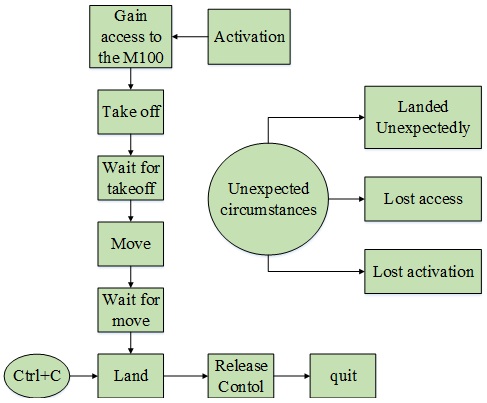 Figure 2 – Docking Activity Flow
c. Cyberphysical architecture
Our cyberphysical architecture can be broken up along its major subsystems and those subsystems’ supporting subsystems.
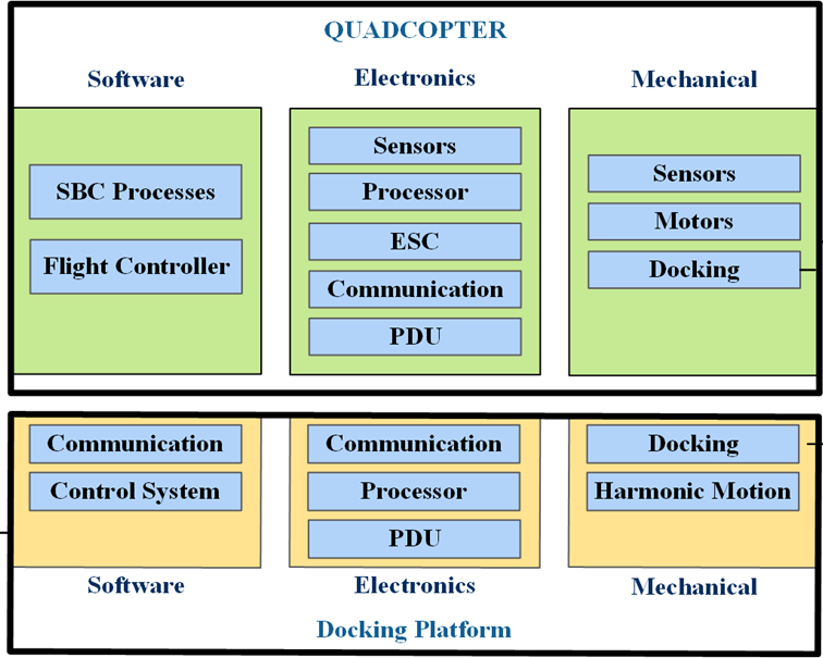
Figure 3 – Cyberphysical Architecture Overview
The dock and quadcopter have their own cyberphyiscal architecture, broken up into power, data, and code.
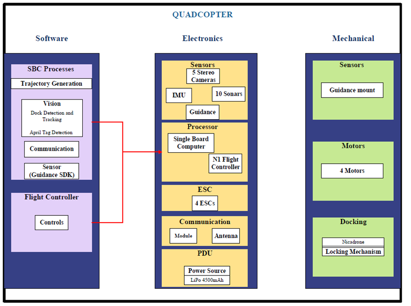
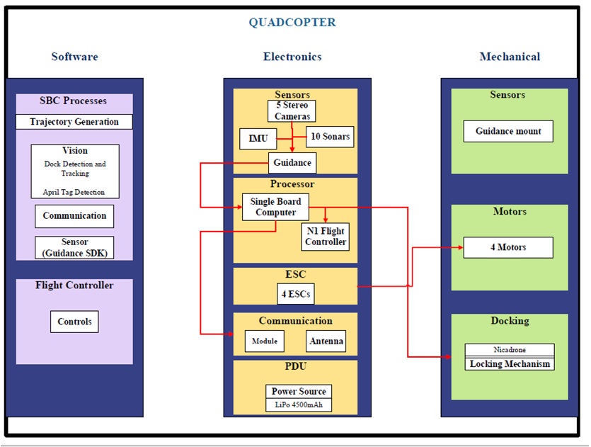
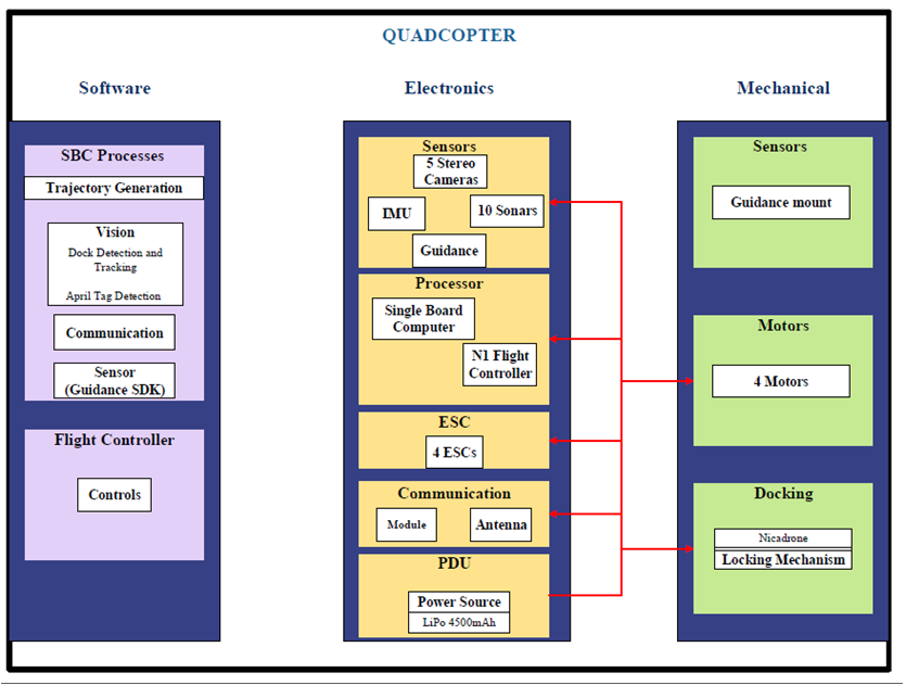
Figures 4-6 – Quadcopter Cyberphysical Architecture : Code, Data, Power
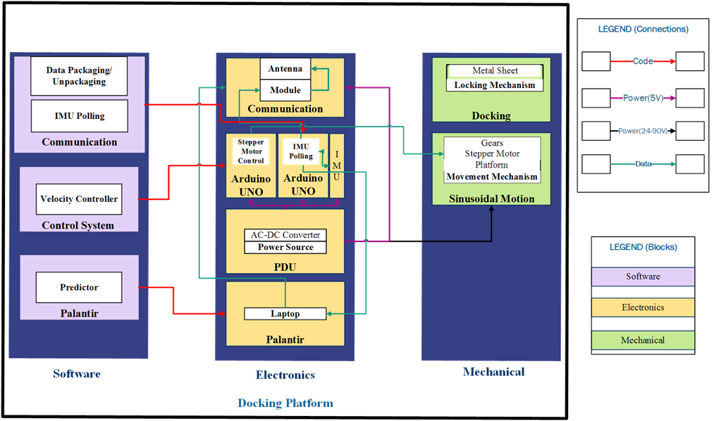
Figures 7 – Dock Cyberphysical Architecture
d. System design description/depiction(s)
The architecture, shown in Figure 2 is divided into three abstractions for the docking platform and the quadcopter. The software abstraction encompasses the algorithms used to accomplish the functions depicted in the functional architecture. The electronic abstraction shows the different electrical equipment and their connection to run the algorithms from the software abstraction. The lines from the software abstraction show which processor runs the processes. Lastly, the mechanical abstraction holds the mechanisms that allow the software algorithms to manifest into the physical realm. The most substantial mechanical feature is the docking mechanism that will lock the quadcopter onto the platform.