Current Overall System Structure 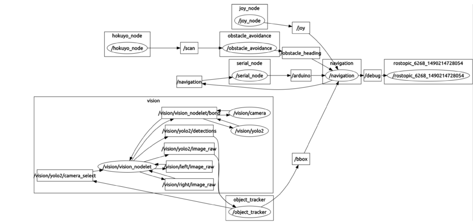
Current overall ROS structure for Mell-E
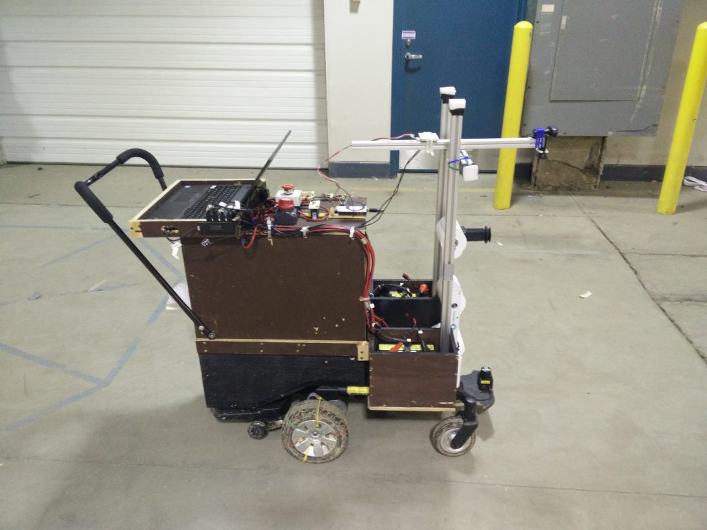
Figure above shows the current structure of nodes and topics that are being used in various systems. After refactoring the code, now we only have one topic to which the Arduino is subscribed to and only one topic to which the Arduino publishes data. The rest of the heavy lifting is to be done by the PC node. The PC node would handle the state switches, generating motor speed values and navigation. The Arduino would just act as an executor where it runs the motor commands received from the PC node and pass the data from the GPS and magnetometer unit to the PC node. As part of the refactoring, we also included a watchdog that would kill the motor if there is a disconnect between ROS and Arduino (an issue that we faced a lot last semester). This made the Arduino code much cleaner and less reduced the load on the Arduino. Robot base current pictures: 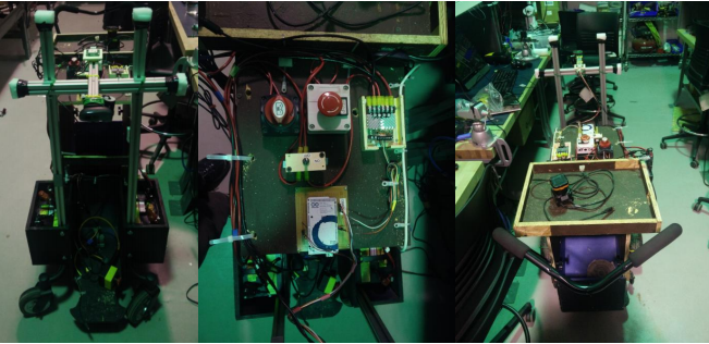
In the sections below, we will explain each of the subsystems in more depth. For a more in-depth explanation of how each subsystem interacts with each other, please refer to the poster and the final report as it provides a much clearer view than what could be reproduced in WordPress layout scheme.
Current System Status: Modeling, Analysis, Tests
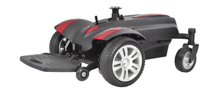
Our team was provided with a mobile base from our sponsor, CloudMinds. Specifically, the mobile base we were provided with was from a powered wheelchair. As such it needed quite a few modifications in order to meet our system’s needs. In order to make the modifications, we had to remove a lot of the aesthetic components of the wheelchair and build our own holders atop the chassis on which to mount the various subsystems. The sequence below shows the transitions of the base from its initial state to the final model:
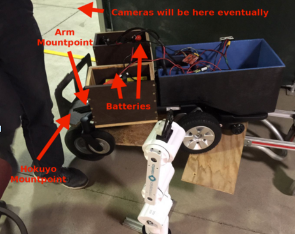
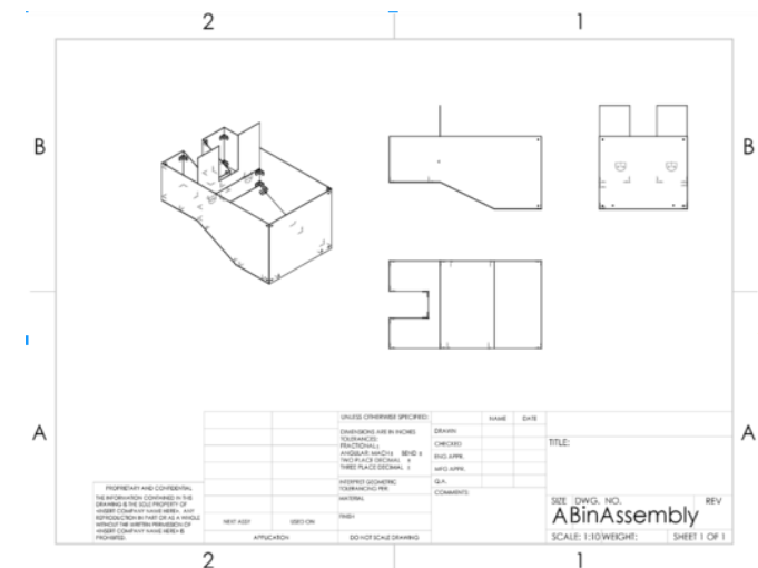
To ensure the chassis components that we built would be compatible with our wheelchair base, we took measurements of the mobile base and modelled the holders in Solidworks. The CAD model is shown below. Upon modelling the holders and making drawings, our team went to the woodshop and built the holders. Although the final system will likely use holders made from plastic, we opted to build the initial holders out of wood to conserve time and ensure we had a working system in time for the FVE.
Beyond modelling the mechanical components of Mell-E, we implemented tests in our software to ensure the communication infrastructure runs smoothly. Specifically, we implemented constraints on the APIs to validate that the data sent to the APIs are well-formed. In addition, simple unit tests were written to ensure improperly formed data is rejected from the server. Although the backend has measures in place to prevent invalid data being entered into the database, the frontend Android application currently doesn’t handle these errors. One thing that we wanted to add but did not get time to add was error checking on the Android app side. There are a few simple safeguards against bad inputs but its not exhaustive.