System Requirements
Mandatory Performance Requirements
- Localize within 1 meter in a pre-mapped area
- Detect 85% of static obstacles while operating indoors
- Travel up to 5 mph unloaded
- Notify user within 2 meters of possible collision
- Classify obstacles as moving pedestrians 70% of the time
Mandatory Non-functional Requirements
- Weigh less than 30 lbs
- Fit within an average carry-on suitcase dimensions: 22 x 35 x 56 cm
- Take less than 10 min for user to calibration
- Operate on different surfaces
- Able to operate on a 5° incline
- User can override any external actuation
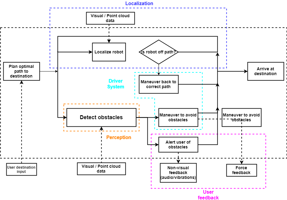
Functional Architecture
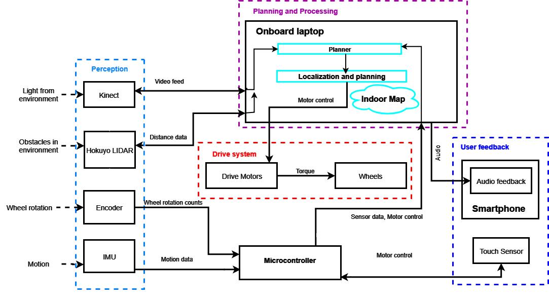
Cyberphysical Architecture
System design description
Cabot comprises of five main subsystems: indoor localization, perception, drive, HCI and path planning. Each subsystem communicates with other subsystems, as depicted in the figure above.
Indoor Localization
For the first iteration, CaBot used BLE beacons and a pre-generated map of the building to localize itself indoors. Small BLE beacons were placed in the hallways of the building and their positions were recorded in a map. Each BLE beacon broadcasts a unique ID, and CaBot measured the Received Signal Strength Indicator (RSSI) of the surrounding BLE beacons to determine its position. CaBot fetched a map of the current building from a map server, which marked the location and floor of every BLE beacon and includes points of interest (POI). CaBot used the BLE ID in conjunction with the map to localize itself. With this method, the localization accuracy was around 1.5 meters which was not precise enough to successfully navigate through the hallways. Our requirements called for CaBot to localize within 0.5 meters so we had to change our localization method.
One alternative we considered to BLE beacons was to use Wi-Fi signal strength. This approach would allow CaBot to enter new buildings without requiring beacons to be placed beforehand. The main drawback of Wi-Fi is that we can’t guarantee strong signal strength in all parts of the building.
CaBot currently uses the Hokuyo laser scanner to localize in indoor environments. We must map the area where CaBot will operate. The user can use the remote control user interface, that is further described in the HCI section, to move the robot slowly throughout the area. CaBot is compatible with the ROS packages gmapping and hector_mapping for creating and saving a map. Our system currently uses the amcl ROS package to localize. This package uses the map that we created, laser scans and transform messages to accurately estimate pose. The transform comes from the odometry information which includes encoder and IMU information. Our transition to the ROS Navigation stack helped CaBot become a much more robust, stable platform.
7.1.2. Perception
The perception system’s job is to avoid obstacles and detect pedestrians. CaBot uses two different sensors for perception: a laser rangefinder for obstacles detection and Kinect One for pedestrian detection. The Hokuyo laser scanner registers the distance it detects on the costmap. Since the Hokuya has a high scan frequency, it is possible to detect obstacles that appears suddenly. The pedestrian detection is implemented with NiTE toolbox, which is an advanced and robust 3D computer vision middleware. The NiTE algorithm uses RGB data from the Kinect, utilizing the OpenNI2 SDK. NiTE2 extracts the skeleton information to track the skeleton precisely.
7.1.3. Drive System
The drive subsystem consists of two geared DC motors used to guide the user around obstacles. There is one motor on each side of CaBot in a differential driver configuration. Initially we were using stepper motors, however these motors did not get up to the speed we wanted. They were hitting their resonance frequencies and locking up at low speeds. We swapped the stepper motors for brushed DC motors, which provided much more consistent performance. In our first iteration of CaBot, we used an L298 motor driver which lacked overcurrent protection. As a result, we blew out the motor driver several times in both semesters. We decided to switch to a Sabertooth motor driver, which can produce more current than the motors can draw during stall. Additionally, it has over current protection. It has proven to be much more reliable and effective for our platform.
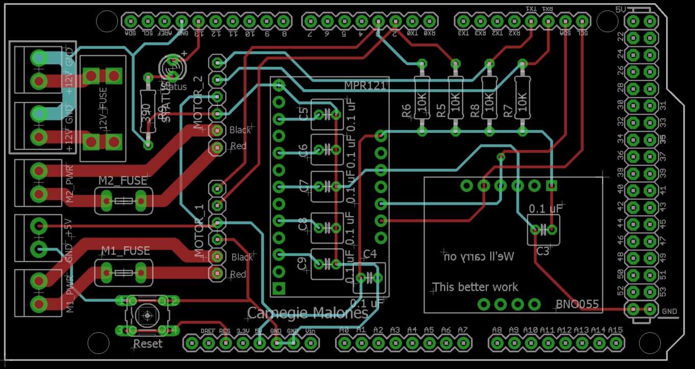
We have designed and integrated a PCB (figure 7) that combines power, sensors, and segments of our drive system on a single board. We went through several iterations of the PCB and settled on a design that was more modular than we had initially planned. Initially, we planned to integrate the motor driver and sensor breakouts for the touch sensor and IMU on a single board. However, we decided to separate the motor driver from the PCB due to multiple motor driver burnouts (as mentioned above) and a design error in the original PCB. Our rationale for making the PCB more modular was to decrease repair times: if the motor driver burned out, we can easily swap it out with a spare motor driver. Our original design had an insufficiently small separation between the traces and the ground plane. As a result, 5V and ground were shorted together. In the final design, we removed the ground plane and the L298 motor driver chip. Additionally, when populating the second PCB design, we made sure to test each section of the board separately before continuing to solder components onto the board.
7.1.4. HCI subsystem
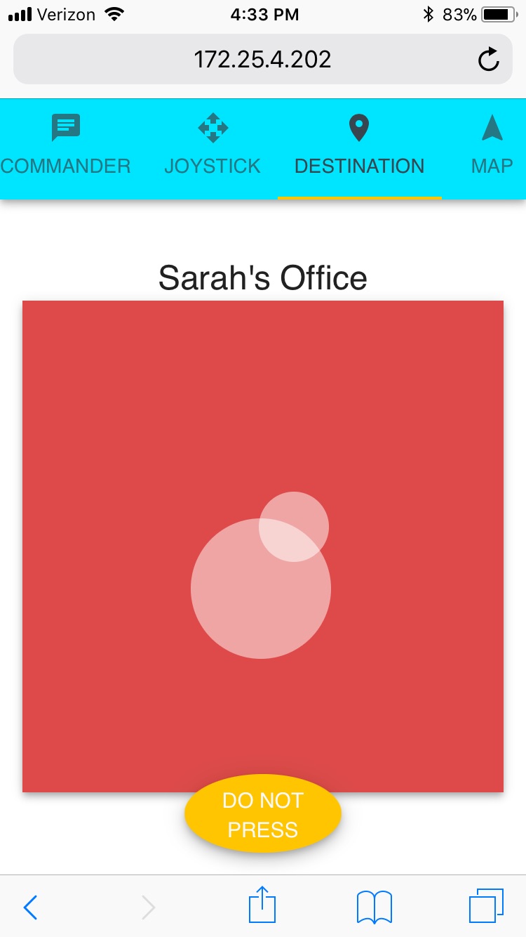
As an assistive robot, CaBot must effectively communicate with its user to be valuable in its role. CaBot provides audio directions to the user, such as “turn left in 6 feet.” Additionally, CaBot alerts the user immediately before they need to change their direction, or if there is a pedestrian in the direct path of the user. We are using user’s mobile device to the interface between the user and CaBot. Our team must consider the volume of ambient noise in the operating environment, and whether the user can hear the verbal commands over background noise. We have a web interface in which the user will be able to choose a destination. The sound is also emitted from the phone so that it is close to the user and appropriately loud. The design for this interface was inspired by the assistive touch interface on iOS. The user has access to a dial that will relay the current selected destination through voice. Once the user hears their desired destination they can let go and CaBot will navigate safely to the final destination. Figure 8 below shows the CaBot also is equipped with a touch sensor on the handle. This is currently used to make sure that CaBot is only moving when the user is touching the handle so that it does not run away from its user if they decide to stop.
7.1.5. Path Planning and obstacle avoidance
The planning subsystem creates a global plan from the current position to the goal position and does local planning to keep on its path and avoid obstacles on the way. This subsystem is tied very closely with the localization system as the planner continually gets estimates for the position to make sure we are able to get to the final destination. For our first prototype, our team integrated the preexisting NavCog app, developed by Dr. Kitani’s lab, into our robot to provide a global plan. The phone provided path data that the laptop uses to help decide where the robot should move. We had to modify certain parts of the app to be compatible with CaBot. For instance, the app assumes the user will be walking, so it counts steps (like a pedometer) to assist in measuring how far the user has traveled. We replaced the step counting functionality with a feature that counts wheel rotations using encoders. Our first iteration used a custom built local planner that was basic and did not account for or re-plan for unexpected obstacles in the path. This was a basic PID controller on the trajectory. This was when we were using the bluetooth beacons for localization and had to rely heavily on the encoders to get good estimates of pose.
We completely overhauled the planner during our next iteration to work well with our newly modified LIDAR localization subsystem. This was designed to integrate completely with the ROS navigation stack. We are using the ROS navfn package as the global planner. This is a fast interpolated navigation function that creates plans for CaBot using a costmap from the created map to find a good path from the start to the end point. This package uses Dijkstra’s algorithm to find the path. In order to keep the local plan and navigate around unexpected obstacles we are using the dwa local planner package in ROS. This uses a dynamic window approach which samples a possible forward trajectory of the robot and then predicts what would happen in that time frame. It computes the cost of the many of these simulated forward steps and then chooses the lowest cost commands to send to the mobile base. It continues to do this as it makes its way through the global plan. There were a lot of parameters we tuned with respect to these planners. Some of the main parameters we tuned were the maximum and minimum velocities and accelerations to make sure the user would have a smooth path. We also had control over the path distance bias and the goal distance bias. This specified how much CaBot would be allowed to deviate from its original route and how often it would decide to replan if it was too far off from the intended route.