Spring Subsystem Description
Drone Platform
The drone platform subsystem consists of a mobile, aerial base and the sensors are mounted to it. It consists of all the components necessary for achieving basic flight, including the drone’s mechanical frame, motors, propellers, motor controllers, IMUs, GPS, flight controller, batteries, and the electronics to drive the motors. Based on the system-level trade study, it was chosen to use a multi-rotor, and from the subsystem level trade study, the DJI M600 Pro was selected.
The M600 drone platform features a flight controller with a UART interface through which an onboard computer can interface. The flight controller handles control of the drone to achieve a given position, velocity or set of waypoints. The flight controller also handles fusing the IMU and GPS sensor data to estimate the drone pose. Communication on the onboard computer with the flight controller will be performed using a ROS wrapper of the DJI Onboard SDK.
Subframe
The subframe subsystem is responsible for connecting all additional hardware components to the frame of the drone platform. It consists of the subframe and camera mount components from the cyber-physical architecture. The hardware components that it must connect to the drone frame include a radiometric camera, two thermal cameras, an RGB camera, a telemetry module, and an onboard computer.
The thermal camera optics originally consist of multiple thermal cameras mounted on angled mounts with angles that can be manually adjusted. However, after obtaining a radiometric camera, we have entirely switched to using the new camera. Currently, the camera attached to a mount that is angled vertically down.
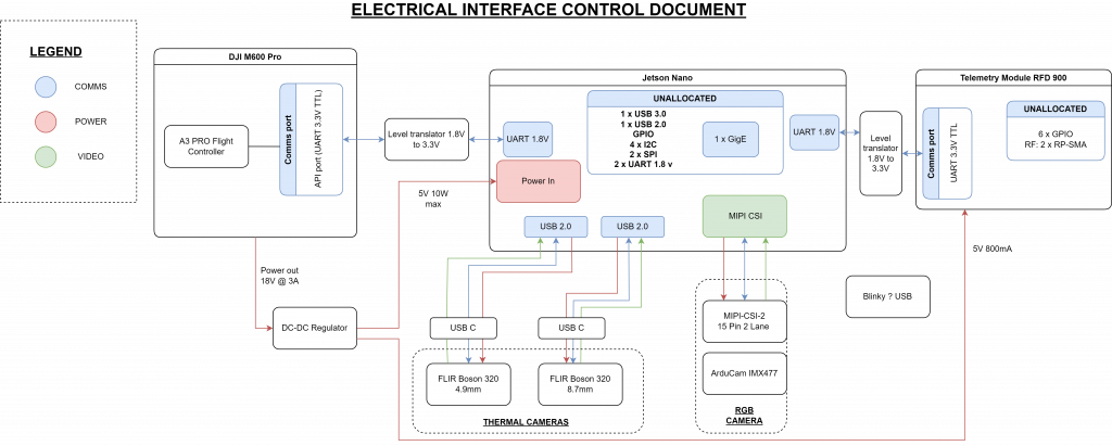
Electrical Framework
The electrical framework subsystem consists of the wiring and electrical connections between all hardware components.
Onboard Computer
The onboard computer is responsible for running the system’s perception, mapping, and planning software and communicating with the DJI flight controller. For the onboard computer, the NVIDIA Jetson Xavier NX has been chosen. The Xavier NX also communicates with the DJI’s flight controller via UART.
Telemetry and Base Station
The telemetry and base station subsystem is the interface between the drone and the operator. It handles the packaging and sending of the data to the base station computer, where the data is displayed for the operator. Telemetry will be sent over radio using an HKPilot v2 Telemetry Module. The base station will visualize the fire perimeter sent from the drone using Python and Matplotlib. A command-line script will be created for sending commands from the base station to the drone.
Fire Perception
The fire front perception subsystem is responsible for detecting if an image contains fire
The fire perception sensor subsystem originally consisted of 2 thermal cameras, the FLIR Boson 640 4.9 mm and FLIR Boson 640 8.7 mm, and an RGB camera, the Arducam 12MP IMX477. while working with this setup, the team had investigated fire detection through two different methods: using a U-Net binary classification model and through a signal processing approach.
We have since switched to the Seek radiometric thermal camera, and are now able to threshold the fire from the input image directly.
Out system is currently being tested with fire “hotspots” which only appears as a cluster of very few pixels. In the future, we are hoping to be able to detect the edge of larger areas fire in the image, which would correspond to a fire front.
Mapping
The mapping subsystem will create and maintain a global fire perimeter map. This would include localizing the edge of the fire in the global frame.
Currently, the map consist of grid cells, which are marked based as either fire or not fire. This is done using the GPS coordinates of the drone and ray-tracing. When the drone is flying over an area, the ground station can give the drone a “capture” command it will tell the drone to take its perceived from from the radiometric camera and project the data onto a global map. During ray-tracing, the fire region is assumed to be flat for simplicity.
For our future work, we will need to differential the fire perimeter to the fire area itself. Also, if there is additional time, an alternative will be to utilize GIS data to take terrain elevation and slope into account when ray-tracing to determine which grid cell is on fire.
Fire Monitoring Path Planner
The fire monitoring path planner subsystem is responsible for generating paths for the drone to follow, allowing the drone to perceive the entire fire perimeter to generate a global map. This is important because the drone will not see the entire fire perimeter from a single location.
The Importance-Based, Alternating Direction path planner as described in this reference will be used. Based on an importance metric, this planner switches between traveling clockwise and counterclockwise around the perimeter. The planner takes in a global map of the fire perimeter represented as cells in a grid. For each fire front cell, an importance value is calculated based on an estimate of how far the fire will have traveled once the drone reaches that cell since the previous visit.
Fall Subsystem Updates
Drone Platform
The only change to this subsystem was when, during one of the field tests, a bug caused the drone to disarm from a height of ~1 m. The drone crash landed, causing damage to 2 of its arms. The arms were fixed by replacing the broken parts which were acquired from a spare M600 drone.
Subframe
The hardware on the drone underwent quite a few changes, based on updates and changes to our requirements. The changes include, the addition of a Seek S304SP radiometric thermal camera for fire detection, a Velodyne VLP-16 LiDAR for terrain mapping, and an RFD 900+ telemetry radio for long range communication.
Telemetry and Video Streaming
Since one of the sponsor requirements was to operate the drone at range of about 1 km, and stream a live video feed back, the Telemetry subsystem underwent significant changes. The HK Pilot v2 radio was replaced with an RFD 900+ telemetry module, with a specified range of close to 20 km. For streaming back video, DJI’s own hardware call the Lightbridge 2, already integrated with the drone, was utilized.
Fire Perception
The perception subsystem is responsible for taking images from the thermal camera, segmenting the fire in the image, stamping this image with the current pose of the camera, and then passing the segmented image and pose to the mapping node.
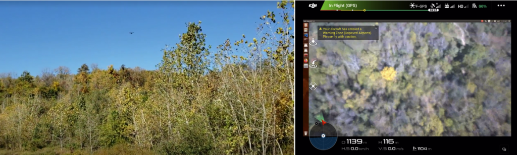
The perception node segments the fire from the thermal images by applying a fixed threshold. The Seek S304SP thermal camera provides absolute temperature thermal images, so the threshold is set to a fixed temperature. The current threshold of 50 degrees celsius was determined empirically based on flight test recordings of portable camping stoves. This was found to be sufficient with minimal false positives and false negatives for an operating height of 15 meters. The only false positives discovered were from the tops of stationary cars underneath direct sunlight. Future flight tests at controlled burns will help determine if a higher threshold can be used. The team expects that the higher intensity heat from a fire will allow a higher threshold to be used, eliminating false positives from car roofs.
Mapping
The mapping subsystem is responsible for building and maintaining an occupancy grid map of the fire. The mapping node takes in pose-stamped, segmented images from the perception node. It then projects these images to the ground plane and merges the projections with the global fire map. Finally, it outputs the fire map updates to the onboard telemetry node which sends these updates to the ground station for visualization.
When the mapping node receives an image, it uses the camera’s intrinsic and extrinsic matrices to calculate rays passing from the camera center through each pixel. For each pixel in the image, it determines the point where this ray intersects with the ground plane. If this intersection point is within the bounds of the fire map, the node will determine the corresponding discretized bin. Once the bin is determined, a naive method is used to merge this information with the global map. If the pixel being projected is a fire pixel (value of 1), the bin will be set to 1 (meaning 100 percent probability of fire) regardless of the prior value of the bin. If the pixel being projected is a no-fire pixel (value of 0), and the bin has a prior value of 0 (0 percent probability of fire) or 0.5 (meaning the bin has not yet been mapped), the bin will be set to 0. Finally, if the pixel being projected is a no-fire pixel, but the bin has a prior value of 1, the bin value will not be changed. The result is that once a bin is labeled as fire, it will remain as fire. While naive, this simplistic approach has proven to suffice for meeting the team’s performance requirements for mapping a stationary set of hotspots.
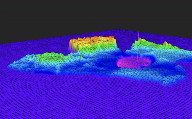
Terrain mapping was a big addition to the mapping pipeline this semester. A Velodyne LiDAR was mounted onto the drone, and was used to generate a terrain map for the surroundings, as well as maintain the drone’s altitude from the ground. A 2.5D terrain map was generated using the LiDAR data. Grid-map by ANYbotics was used to store and visualize the terrain map. A terrain map generated during one of the flight tests can be seen below.
Planning
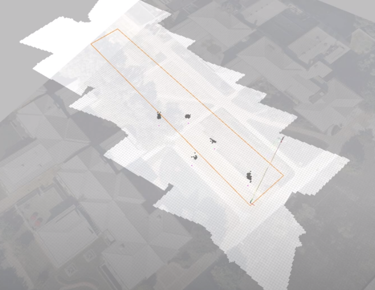
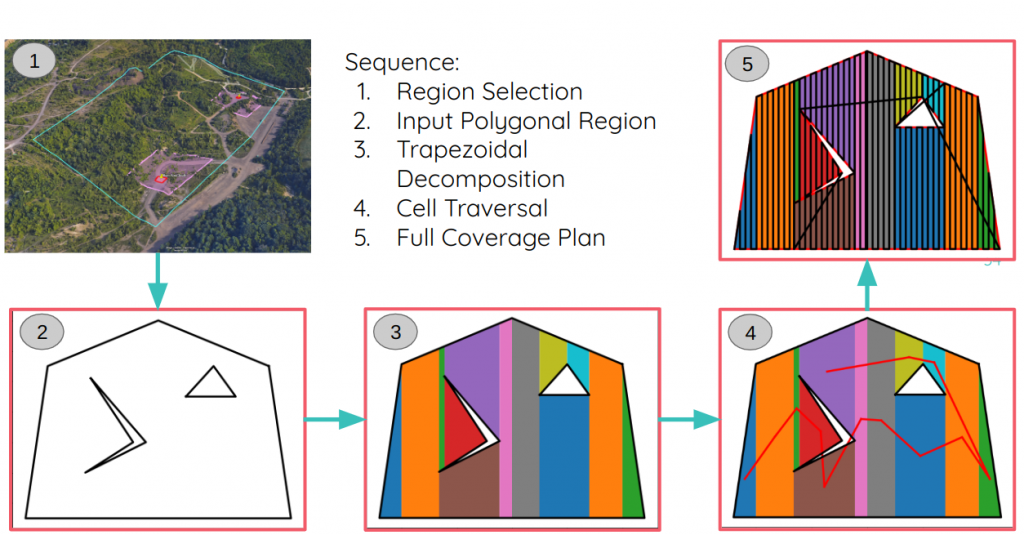
The team decided to implement a fire coverage planner. The intended use of this planner was to send a demarcated area/polygon using google earth, so that the drone can plan a path suitable to cover the entire area and check for fires. The path output by the planner is then passed on to the trajectory controller, which generates control commands to follow the particular path. The sequence of steps as well as the output of the planner for an input polygon can be seen below.
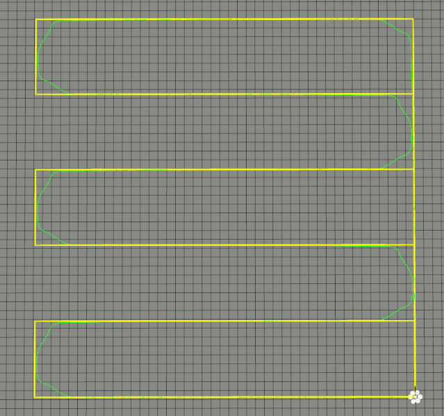
The actual trajectory followed by the drone based on an input lawnmower trajectory can be seen below.
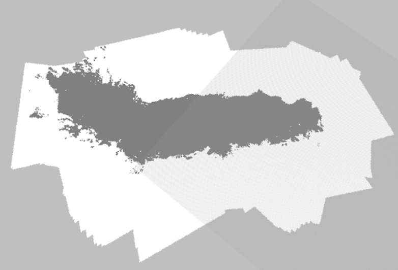
The input polygon, and the output region mapped, along with the fire hotspots can be seen in the image below.