System requirements
Requirements
| Functional Requirement | Performance Requirement | Justification/Assumptions |
| M.F.3. Plan path & traverse to the desired location | M.P.1. Traverse on hard, flat indoor floors reliably at 0.4 m/s during teleoperation | Presence of limited obstacles in the surrounding such that a path exists for robot to avoid obstacles and traverse ahead |
| M.F.3. Plan path & traverse to the desired location | M.P.2. Reach the desired location within 30 minutes | Assuming latency in receiving user input, obstacle detection, avoidance, and arm manipulationGoal location in the operating area and 100m away from start location of the robot |
| M.F.1. Facilitate remote user accessM.F.2. Receive inputs: room location and teleoperation | M.P.3. Receive user input from interface with a latency less than 5 seconds | Assuming >100mbps broadband connectivity is available to user and robot |
| M.F.3. Plan path & traverse to the desired location | M.P.4. Plan global path to the desired location within 3 minutes | The algorithms of the system will be optimized to use onboard compute capability to achieve this |
| M.F.4. Detect and avoid obstacles | M.P.5. Detect and avoid obstacles (during autonomous navigation and teleoperation) with mAP of 80% | For obstacles lying in the FOV of sensing modalities |
| M.F.6. Detect objects for object grasping and placement. | M.P.6. Detect objects with a precision of 70% and recall of 60% | For predefined set of objects in the environment and appropriate lighting |
| M.F.7. Estimate grab points and pose of the objects | M.P.7. Estimate grab points and pose of objects with a precision of 65% | For predefined set of objects in the environment and appropriate lighting |
| M.F.8. Plan manipulator motion for object grasping and placement | M.P.8. Plan manipulator motion to grasp object within 3 minutes | The algorithms of the system will be optimized to use onboard compute capability to achieve this |
| M.F.9. Autonomously grasp and release object | M.P.9. Grasp or release object within 5 minutes, with 67% success rate (2 successful trails out of 3) | Accounting for slippage of end-effector due to physical properties (torque required, material) of objects |
| M.F.10. Provide gimbal control of tablet | M.P.10. Provide gimbal motion of 60 degrees in pitch and 120 degrees in yaw for the display device | To mimic natural human perspective FOV |
| M.F.11. Provide a video call interface to user | M.P.11. Provide a 1080*720 resolution video call interface for user to interact with surroundings with a lag less than 2 seconds. | The system aims to provide a HD and a real-time experience to the user |
| M.P.12. Provide traversal feedback | M.P.12. Provide traversal feedback to user every 5 seconds | The system aims to provide a real-time experience to the user |
Mandatory Performance Requirements
| PR# | Description |
| PR1-M | Reach the desired location within 30 minutes (Desired location distance <=150 m) |
| PR2-M | Traverse on hard, flat indoor floors reliably at 0.4 m/s during teleoperation |
| PR3-M | Receive user input from interface with a latency less than 5 seconds |
| PR4-M | Plan global path to the desired location within 3 minutes |
| PR5-M | Detect and avoid obstacles (during autonomous navigation and teleoperation) with mAP of 80% |
| PR6-M | Detect objects with a precision of 70% and recall of 60% |
| PR7-M | Estimate grab points and pose of objects with a precision of 65% |
| PR8-M | Plan manipulator motion to grasp object within 3 minutes |
| PR9-M | Grasp or release object within 5 minutes, with a 67% success rate (2 successful trials out of 3) |
| PR10-M | Provide gimbal motion of 60 degrees in pitch and 120 degrees in yaw for the display device |
| PR11-M | Provide a 1080*720 resolution video call interface for users to interact with surroundings with a lag less than 2 seconds. |
Desirable Performance Requirements
| PR# | Description |
| PR1-D | Reach the desired location within 20 minutes(Desired location distance <=150 m) |
| PR2-D | Detect and avoid obstacles (during autonomous navigation and teleoperation) with mAP of 90% |
| PR3-D | Plan manipulator motion to grasp/place objects within 3 minutes |
| PR4-D | Grasp or release object within 5 minutes, with an 80% success rate (8 successful trials out of 10) |
| PR5-D | Provide traversal feedback to the user every 5 seconds |
Mandatory Non-Functional Requirements
| NFR# | Description |
| NFR1-M | Provide a user-friendly interface with a small learning curve. |
| NFR2-M | Be modular with APIs to facilitate further development |
| NFR3-M | Be situationally aware |
| NFR4-M | Be friendly to facilitate natural interaction |
Desirable Non-Functional Requirements
| NFR# | Description |
| NFR1-M | Be deployed in a defined environment in the Robotics Institute. |
Functional architecture
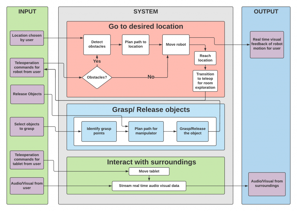
The functional architecture in the figure shows the major functions and the flow of information, energy, and material for TouRI. The core functionality of the system is to facilitate telepresence for a user to tour the defined environment in the Robotics Institute.
The user inputs in the functional architecture are on the left. They are as follows:
- Location input is chosen by the user that the user wants to tour.
- Teleoperation commands from the user for navigation of the robot.
- Teleoperation commands from the user for control of the tablet.
- Audio-Visual data of the user.
The system’s main functions are
- Go to the desired location.
- Grab souvenirs.
- Facilitate interaction with surroundings.
Cyberphysical architecture
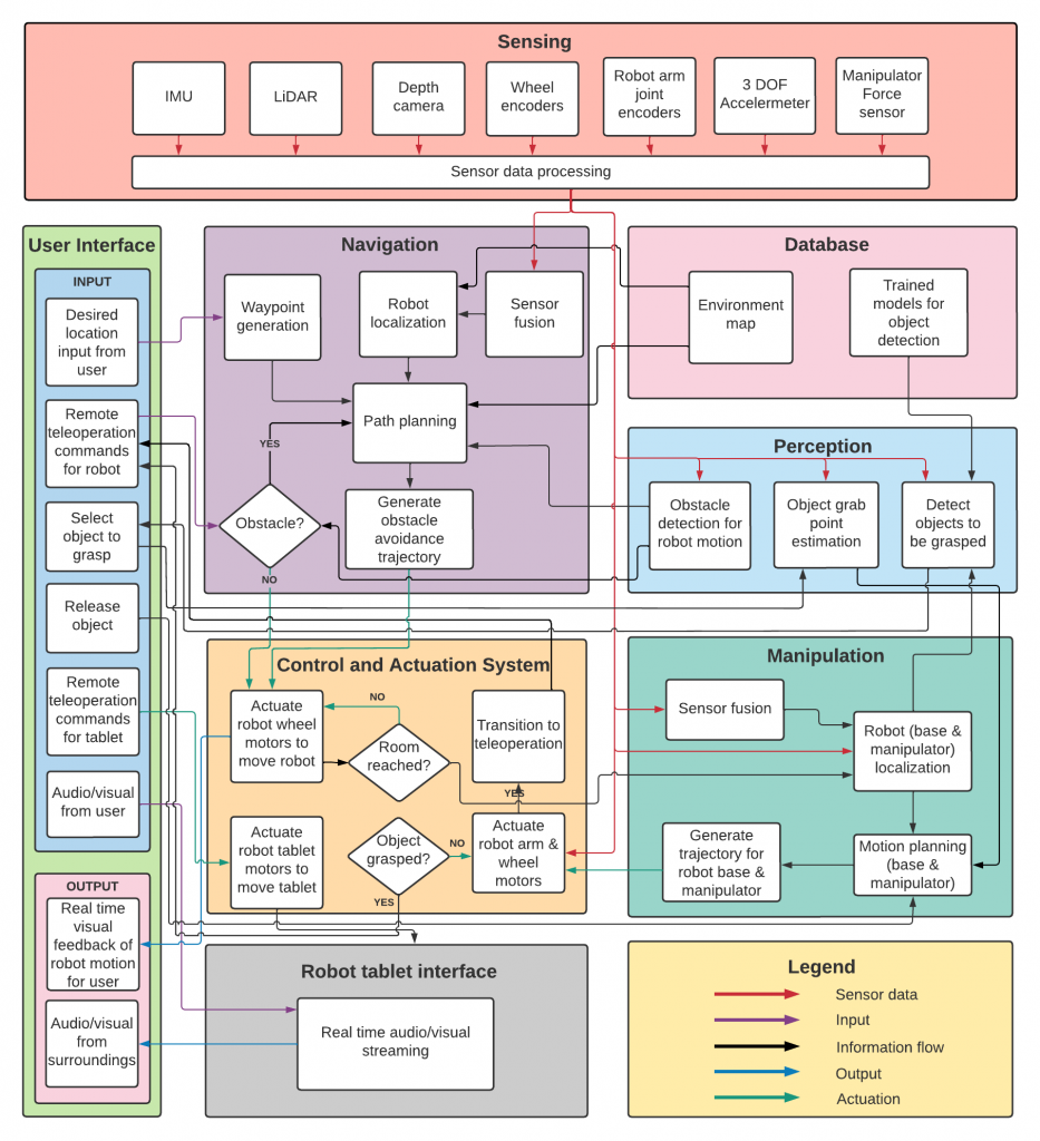
The cyber-physical architecture, derived from the functional architecture, describes the system modules and the interaction between them for the functioning of the system. The architecture has been devised to make the system modular, thereby facilitating adaptability to any modifications that may be made to subsystems for further development or for different use cases. The major modules of TouRI include the following- user interface, sensing, navigation, perception, manipulation, control and actuation, and robot display device interface.
System design description/depiction(s)
Interface
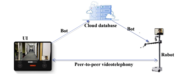
The UI is an iOS and Android mobile application through which users can send commands to the robot and receive updates from the robot. The UI displays real-time audio and video feed of the robot and provides a human-centric design to send autonomous and tele-operational commands to the robot.
There are two communication links – the videotelephony link and the commands link. The video telephony link is a peer-to-peer communication link that streams audio and video of the user and the bot. For heavy exchange of data, like with audio and video streams, Peer-to-peer architecture is faster and more reliable as compared to a centralized architecture.
The command link is a client-server-client link, where the bot and the UI are the clients and a cloud database is a server. The cloud database (Google’s Firebase Firestore) provides real-time updates to listening clients. This architecture provides a single source of truth to both clients and also keep a track of commands and bot state. Lastly, the ease of scalability for this architecture opens up many different future potentials for the project like swarm telepresence.
Navigation

The navigation subsystem facilitates shared autonomy for robot traversal, operating in both autonomous and teleoperation modes.
In the autonomous mode, the navigation module generates a goal waypoint corresponding to the location selected by the user on the interface. Odometry data from the sensors-IMU, wheel encoders, Lidar, and depth camera are fused by the sensor fusion node. The fused odometry is used by the robot localization node to estimate the pose of the robot in the pre-fed map of the environment (generated and stored prior to the operation of the robot). The perception module detects obstacles in the vicinity of the robot and provides information about the obstacle to the navigation module. Based on the current pose of the robot and the goal waypoint, the path planning node generates a global path for the robot. This is augmented by the local plan generated by the path planning node based on the obstacles detected. This trajectory is sent to the control and actuation system to send motor velocities to actuate the wheel motors.
In the teleoperation mode, the teleoperation node receives robot control inputs from the user through the interface. Simultaneously, it also receives information about obstacles detected from the perception module. If no obstacle is detected, the teleoperation node sends a command to the control and actuation system to actuate the motors based on teleoperation inputs. If an obstacle is detected, the user is alerted of the direction in which the obstacle is present so that the user can avoid it. If the user is too close, teleoperation control is retracted from the user in that direction. Control is returned only when user has corrected the robot to a safe distance from the obstacle.
Perception

The perception module is responsible for detecting the souvenir objects and estimating the grasp point of the souvenirs. It is also responsible for the detection of the shipping box to place the grasped objects in the shipping box. The perception module also creates the database using the tracking-based labeling pipeline. This labeled database is used to train the detection model which then is used for the detection of souvenirs and shipping boxes.
The perception module detects objects to be picked up. To achieve object detection detectron2 framework is used. It is trained using a labeled dataset of custom images. Once the object has been detected, the perception module must estimate the grasp points of the object. Combining the bounding box information from object detection and point cloud from the depth camera, the grab points for the objects will be estimated and sent to the manipulation module for autonomous pick and place operation.
Manipulation

The manipulation module is responsible for grasping and placing souvenir items in the shipping box. Based on the data received from the perception module, it plans a trajectory for the manipulator and the base to pick the object and place it in the shipping box. The control and actuation system moves the robot arm and the base according to this trajectory.
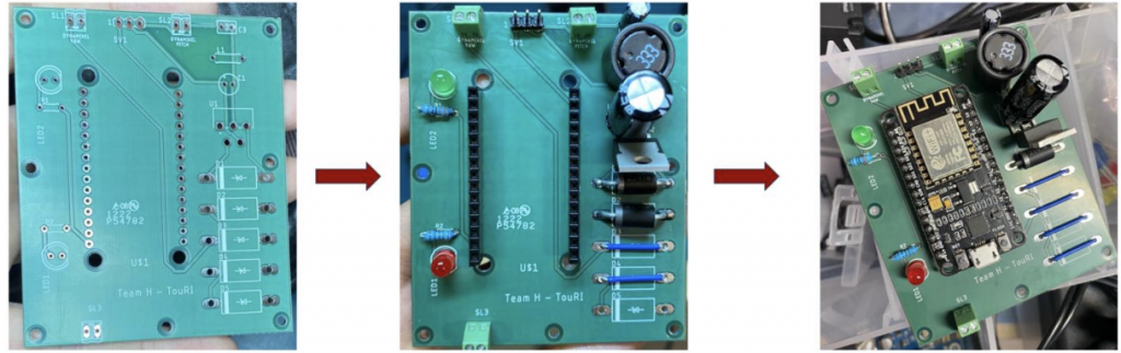
Hardware
This subsystem adds a face to the robot to make the virtual presence of the user more realistic and natural. The user operating the robot can control the gimbal mount to orient the display on the robot through the app interface, for natural interaction with the surrounding. The control inputs are converted into coordinates for the orientation of the display and transferred to the cloud. This data is then received by the task file being managed under the interface module. The ROS package then retrieves this data and passes it to the microcontroller which then converts the coordinate data to pitch and yaw angles for the servos.
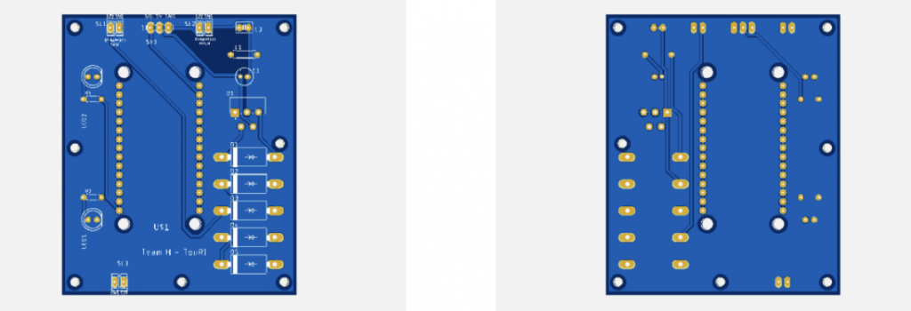
Other developments include various interconnect PCB, Microcontroller based servo motor controllers, and power distribution systems for the project: