Design Reviews
| Conceptual Design Review | Report | Presentation |
| Preliminary Design Review | Report | Presentation |
| Critical Design Review | Report | Presentation |
| System Development Review | Report | Presentation |
| Final Report | Report | Presentation |
Individual Lab Reports
Standards and Regulations
Design Brainstorming
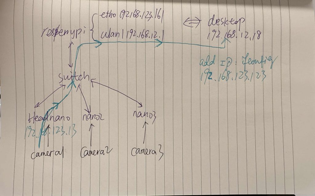
This is the draft for the Unitree network configuration for wireless image transmission. The UDP package flows to switch, then Raspberry Pi, and finally the desktop.
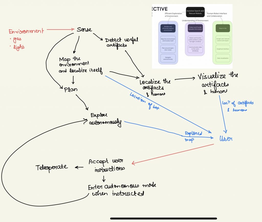
Here is a draft we wrote for system design.
CAD Model
The CAD model of our team is on the page of [System Implementation/Hardware Design and Integration].
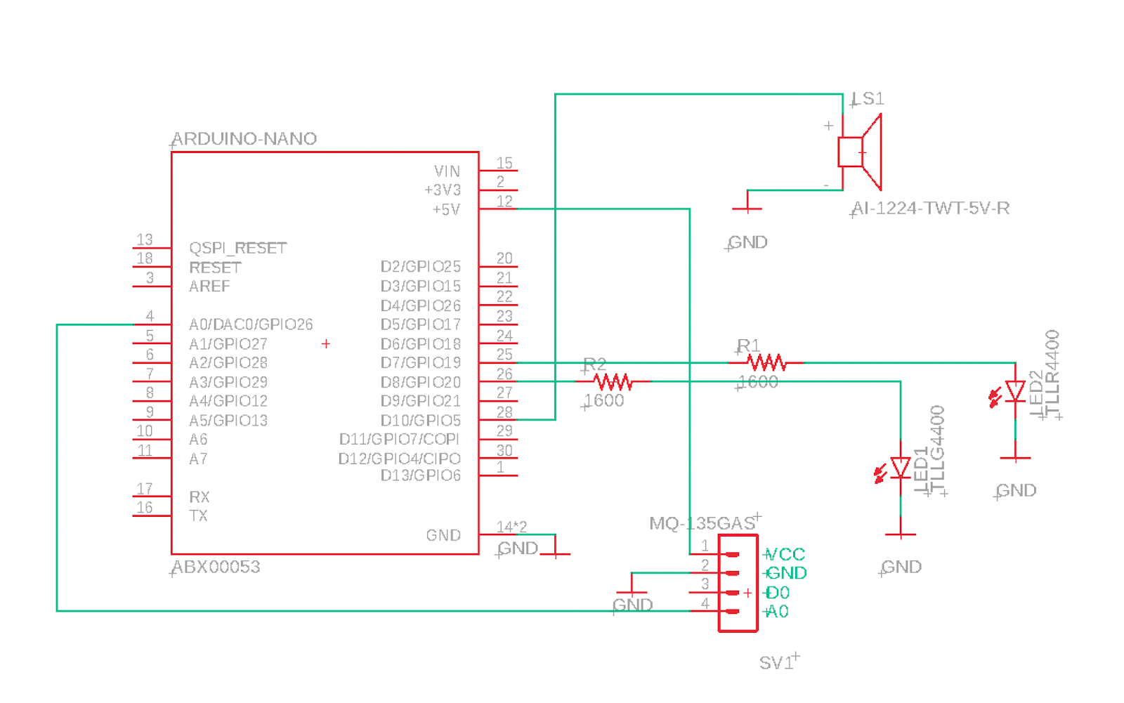
Power Distribution Board: Add-on Gas Detection
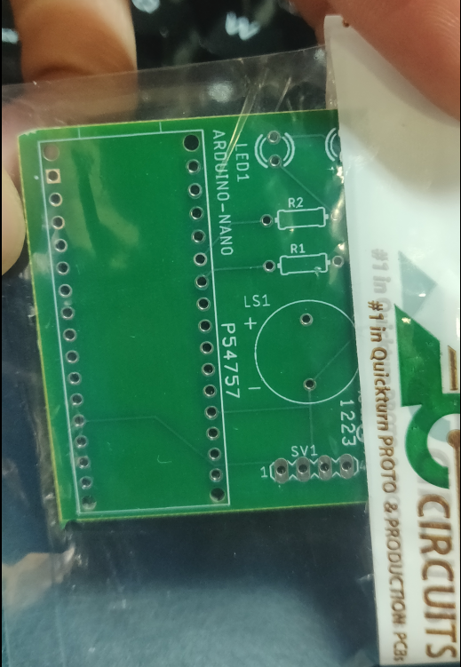
Per PCB design, we developed a breakout board to power a gas detector, LED lights, and a buzzer to serve as a warning device if dangerous gas is detected above a safe threshold. The schematic is shown in Figure XXX below. This Arduino Nano will be powered by the robot payload’s USB port (usage) or by a laptop (demo) via a 5V USB-to-micro-USB cable. The Arduino board will serve as the processing unit to operate the MQ-135 gas detector, as well as buzzers for sound alarms and LEDs for visual warnings.
The basic component BOM is shown in the Table below.
| Item No. | Name | Description | Quantity | Designator Part | Manufacturer Part Number | Vendor for purchase | Cost / part [$] |
| 1 | Arduino-Nano | micro circuit board | 1 | ABX00053 | ABX00053 | Digikey | 30.6 |
| 2 | TLLG4400 | Green LED | 1 | LED1 | TLLG4400 | Digikey | 0.6 |
| 3 | TLLR4400 | Red LED | 1 | LED2 | TLLR4400 | Digikey | 0.51 |
| 4 | R1, R2 | Resistor = 1600 ohm | 2 | R1, R2 | MBB02070C1601FCT00 | Digikey | 0.29 |
| 5 | BUZZER MAGNETIC | Buzzer, 5V, 30mA | 1 | LS1 | AI-1224-TWT-5V-R | Digikey | 1.05 |
| 6 | Pin Header | 1×4; 2.54mm | 1 | SV1 | PPTC041LFBN-RC | Digikey | 0.45 |
| 7 | MQ-135 | Gas detector | 1 | SV1 | 430578031 from Ximimark | Amazon | 8.99 |
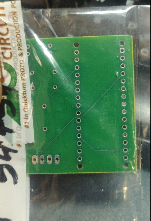
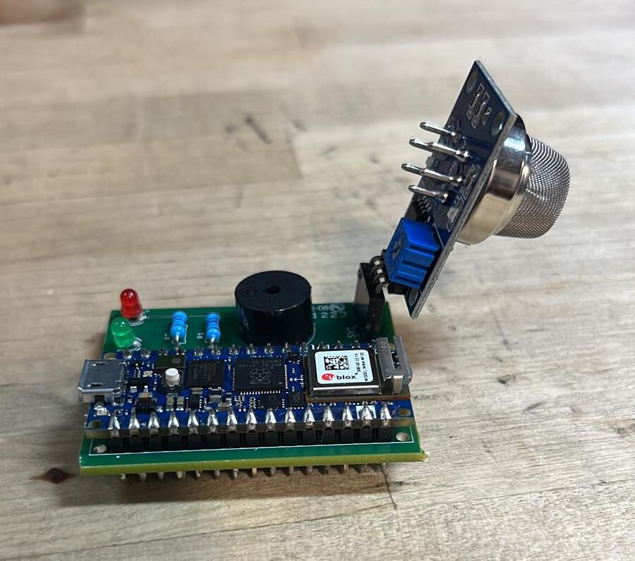
The CAD layout is shown in Figure 2 below.


Drawings, schematics, and datasheets
Electrical: PCB Datasheet
Software Architecture
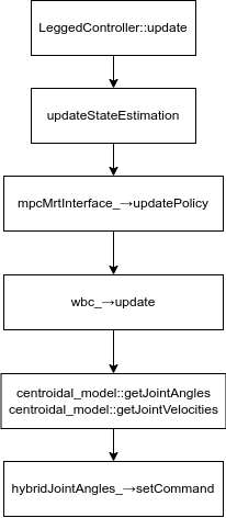
Here is the software follow for the legged control system.
Component testing & experiment results
Human Detection
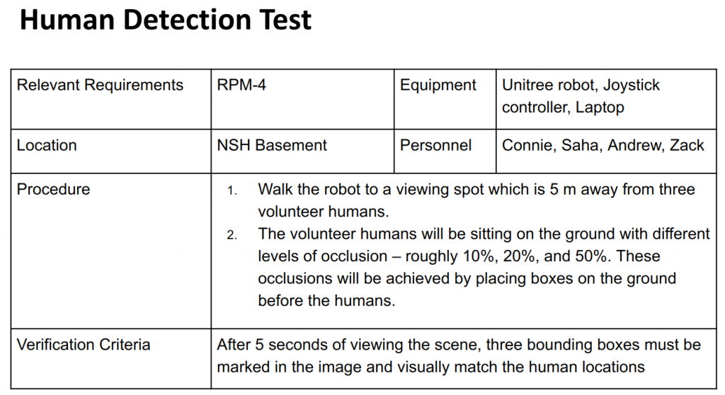
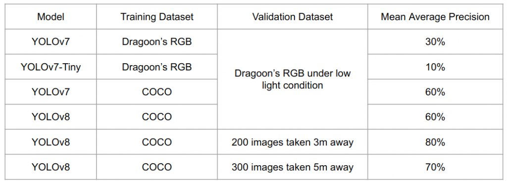

Previously, we tested our system with seniors rgb dataset, but it doesn’t fit our use case because of the low light condition. To further test the human detection system, our team built up a 500 image dataset. We took a video of humans staying 5 meters and 3 meters away from the robot. Making different postures and hiding behind chairs and wood boards. As you can see in the live test, YOLO is very powerful. So we skipped the images that are easy to detect as well as the repeated ones. We handpicked frames that look challenging for the test and close to real disasterous scenarios.
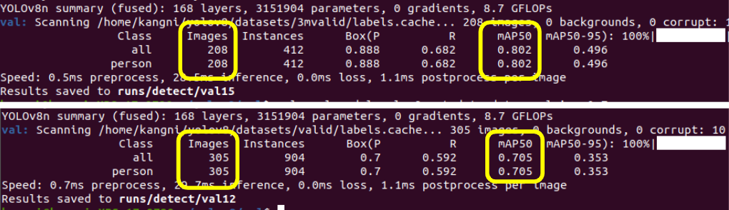
Our system reaches 80% precision with the 200 images taken 3 meters away. And it reaches 70% precision with the 300 images taken 5 meters away.
Payload 3D LiDAR SLAM
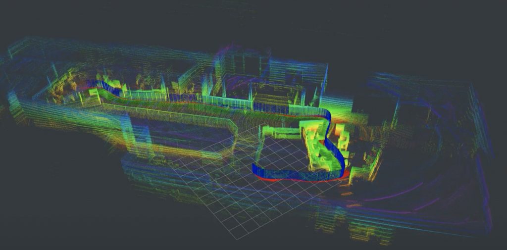
In Figure 11, the 3D pointcloud and motion trajectories are displayed for the tests at AirLab’s Squirrel Hill office and NSH B-level. For the test performed in AirLab, the sensor payload was mounted onto a moving cart, hence producing a cleaner pointcloud upon inspection. For the tests performed at NSH B-level, we increased the difficulty by carrying the payload on the shoulder when recording maps, which mimics the walking gait the payload would experience on a quadruped robot. As shown in the result, the pointcloud becomes more blurry without clear-cut geometries upon inspection, given that larger and more challenging B-level geometry does play an role in the mapping process.
Per our targeted performance requirements for Spring Validation Demonstration and Encore, the payload 3D LiDAR SLAM subsystem was not aim to achieve a specific quantified metric by the end of Spring 2023 semester given the 2-month delayed delivery. The system did shown promising preliminary results to support our end goal in exploration and human localization by producing reasonably accurate trajectories and 3D maps. For future developments, the performance requirement of 3D SLAM subsystem will be met in the first quarter of Fall 2023 semester during progress reviews. The test will be evaluating the absolute Euclidean distance error between start and end pose given they are the same in ground truth.
Software
All code has been developed under version control using GitHub. The software stack is in large part a ROS2 workspace written predominantly in C++. Python is also used for the human detection function. The team also build up docker container and worked on environment agnostic code.
Here is an example our code, which is used for human detection.
Here is another piece of Arduino code, used for CO2 detector.