The system-level requirements of DarkBot are derived from the use case and objective tree. The requirements include functional, performance, and nonfunctional ones, and each of them is divided into mandatory and desirable requirements. By the end of the fall semester, we would achieve all mandatory requirements. The desirable requirements are initially out of scope, but they will significantly enhance the performance of the system. The team will try its best to achieve them as much as possible.
All requirements have been discussed and reviewed by stakeholders to make sure that they are realistic and doable for the project. Note that those requirements are not finalized and will be changed according to future research and tests.
System Requirements
Mandatory Functional Requirements

Desirable functional requirements

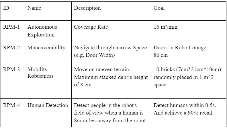
Performance Requirements
Mandatory Performance Requirements
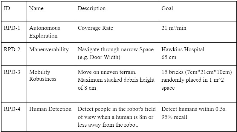
Desirable Performance Requirements
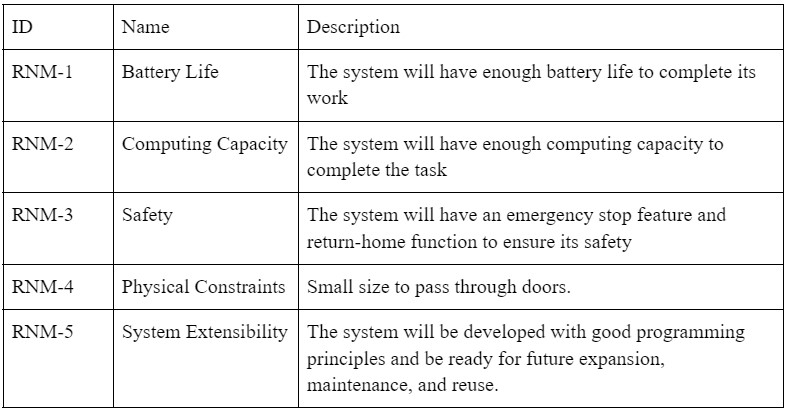
Non-functional Requirements
Mandatory Nonfunctional Requirements
Desirable Nonfunctional Requirements

Functional Architecture
Autonomous exploration and human localization are the system’s core high functions to solve our use case. To accomplish such functions, we compiled the functional architecture from function requirements accordingly. The functional architecture diagram is shown in Figure 1. From a black-box perspective, the system takes in the environment information, operator inputs, and electricity, and outputs robot terrain traversal, a 3D map with robot and detected human poses, etc. This architecture can be broken down into three parallel pipelines: perception-based planning (top), SLAM (middle), and human detection and localization (bottom).
The perception-based planning pipeline (top) first performs a terrain analysis about the surrounding environment of the robot to generate a 2.5D elevation map. This map is used as a prior to a more efficient motion planning that executes the local trajectories and global exploration route generated by the Navigation module, given the 3D map and robot pose from the second pipeline. Second, the SLAM pipeline (middle) continuously builds a 3D environment map with a robot pose estimation from collected sensor data. The map and robot pose serves as a foundation for explorations (top) and human localization (bottom). Third, the human detection and localization pipeline uses color-and-depth image stream data to detect humans in robot’s field of view and localize them in the global 3D map. This end-user will see human location pins on the 3D map, which is achieved with robot pose, human pose estimation relative to the robot, and the visualized 3D map. Last but not least, an operator would have overriding teleoperation access to intervene and control the robot during any circumstances.

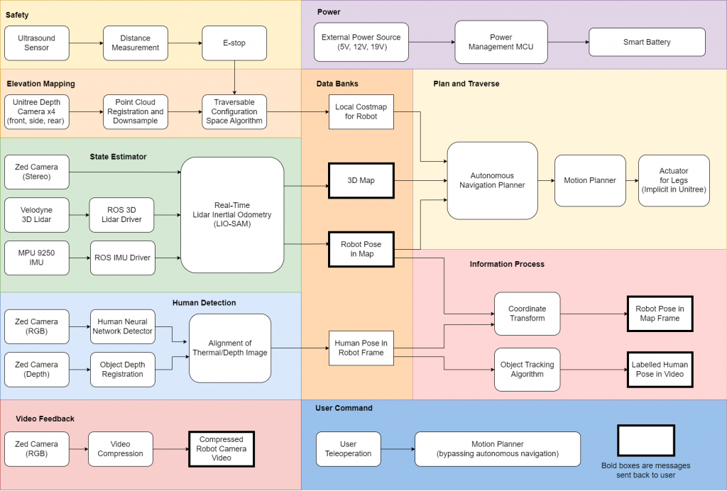
Cyberphysical Architecture
Building upon the conclusions in our trade studies, the cyber-physical architecture as shown in Figure 2 realizes our requirements by combining the functional architecture with the Unitree Go1’s hardware architecture and the sensor payload. The main components of the system are divided into the eight parts: Safety, Simultaneous Localization and Mapping, State Estimator, Human Detection, Video Feedback, Power, Plan and Traverse, Information Process, and User Command.
System Design
Elevation Mapping and State Estimation Subsystem
Following the cyber-physical architecture, the simultaneous localization and mapping (SLAM) module should take 3D LiDAR scans, IMU reading, and Stereo camera data as input and maintain a 3D world map with estimated robot pose. It serves as the foundation for search and rescue exploration through narrow spaces and upon terrains with elevation changes. The SLAM architecture should be robust and reliable as the map grows larger, as well as consistent on runtime and memory consumption to guarantee real-timeness. Further based on the trade study, our SLAM architecture will likely follow the standard formulation proposed in LIO-SAM, which stands for Tightly-coupled Lidar Inertial Odometry via Smoothing and Mapping.
LIO-SAM formulates lidar-inertial odometry on top of a factor graph, enabling both relative and absolute measurements, to perform pose graph joint optimizations and loop closures. The tightly coupled IMU provides nonlinear motion pre-integration to de-skew point clouds, initialization of odometry optimization, and most importantly contributes to part of the factor graph for bundle adjustments. The result of lidar odometry optimization can conversely be utilized to estimate the bias of IMU in the factor graph. To ensure the real-timeliness without sacrificing accuracies, LIO-SAM uses edge and plane features as descriptors proposed by LOAM for 3D lidar scans and achieves critical efficiency in the following:
Computing Lidar Odometry Factor:
- Maintain a fixed-lag smoother (i.e. sliding window) consisting of sub-keyframes for voxel map in the world frame to prepare for scan matching
- Fast data association during local scan-matching whose motion prior is initialized from IMU.
- Non-linear least square optimization (GaussNewton) to compute lidar odometry transformation factors
- Keyframes registrations
Localization:
- Marginalize old lidar scans for pose and trajectory optimization
Computing Loop Closure Factor:
- Place recognition based on baseline metric—Euclidean distance-based detection
- Place recognition mechanism based on more advanced point cloud descriptors
- Fast data association when matching new key-frame to corresponding past sub-keyframes
- Correcting drift in translation and most importantly altitude
Plan and Traverse Subsystem
Building on top of the Elevation Mapping and State Estimation subsystem, the goal of the Plan and Traverse subsystem is to efficiently explore the environment. The exploration strategy can be information-theoretic, frontier-based, topological, random sampling-based, or a hierarchy of these methods.
The TARE exploration strategy is a candidate approach that performs frontier exploration with a minimum set of viewpoints by recursively and randomly sampling the viewpoints. Using the estimated state of the robot and the elevation map (from the previous subsystem), we obtain the traversable configuration space within the robot’s local planning horizon, current viewpoint location, and boundary viewpoints. These are provided as inputs to the planner, which recursively computes viewpoints, concatenates local paths between them, and outputs the exploration trajectory plan. This trajectory plan is provided as input to the traversal APIs of the Unitree quadruped robot.
For a legged robot, the best local path should be determined by the highest foothold score. The foothold score is a function of the amount of time taken to traverse the path and the robot’s ability to find stable footholds in the path. We will use this as the local cost function for the TARE exploration planner.
Human Detection Subsystem
The human detection subsystem makes use of the RGB and depth camera. YOLOv4 processes the RGB image, and marks humans on the image. Human locations on RGB images will be used to locate humans on the depth image. Last, humans on the depth image will be mapped to the 2d world map as points of rescue interest.