
System Requirements
In order to navigate the testbed environment, our AMRs need to map the environment, localize in this map, perceive static and dynamic obstacles, plan paths to reach target destinations, and execute these paths without any collisions. Additionally, we need to interact and communicate with operators and the testbed to pick up and dropoff payloads. See Table 1 for the full functional requirements. Translating these requirements into commitments, we are holding ourselves accountable to the following performance requirements and non-functional requirements presented in Tables 2 and 3. These requirements have been developed based on stakeholder feedback and will continue to be refined.
System Functional Requirements
| Requirement ID | Requirement Description“The system shall ” |
| M.F.01 | Create a map of the testbed environment |
| M.F.02 | Localize in map of the testbed environment |
| M.F.03 | Perceive obstacles |
| M.F.04 | Execute the planned path while avoiding obstacles |
| M.F.05 | Publish real-time task and system status |
| M.F.06 | Receive material handling requests |
| M.F.07 | Pick up and drop off payloads at payload docks |
| M.F.08 | Localize in the map of the testbed environment |
| M.F.09 | Coordinate interactions with human operators |
System Performance Requirements
| Requirement Description“The system shall ” | Mandatory thresholds | Mandatory requirement ID | Desired thresholds | Desired requirement ID |
| Localize in map of the testbed environment with a maximum error of n cm | n = 25 | M.P.01 | n = 10 | D.P.01 |
| Perceive and avoid obstacles within a radius of n meters of the AMR with a minimum recall of r and precision of p | n = 5,r = 70%,p = 70% | M.P.02 | n = 5,r = 90%,p = 90% | D.P.02 |
| Execute planned path from source to destination in testbed environment with an average speed > n m/s | n = 0.25 | M.P.03 | N/A | N/A |
| Execute Pick up and drop off of payload within n seconds of reaching the dock’s vicinity. | n = 60 | M.P.04 | N/A | N/A |
| Dock within a radius of n cm, and within m degrees of desired docking pose. | n = 10,m = 10 | M.P.05 | n = 10,m = 5 | D.P.05 |
| Localize in the map of the testbed environment with a maximum error of n cm | l = 50,w = 50,h = 20,m = 5 | M.P.06 | N/A | N/A |
System Non-functional requirements
| Requirement Description“The system will be ” | Mandatory thresholds | Mandatory requirement ID | Desired thresholds | Desired requirement ID |
| Open-sourced | N/A | M.N.01 | N/A | N/A |
| Reliable: The system shall execute tasks with at least n% probability of success | n = 80 | M.N.02 | n = 95 | D.N.02 |
| Scalable to a fleet of AMRs | N/A | M.N.03 | N/A | N/A |
| Independently demonstrable from the state of the testbed project | N/A | M.N.04 | N/A | N/A |
Functional Architecture

The system is divided into two parts –
- The Offboard System includes the Server and the HRI.
- The Onboard System includes the AMR.
The basic functional architecture consists of a separate stack on the AMR as well as a separate stack on the Server. The Server is designed to handle scalability in the number of AMRs but for the project scope, only one AMR will be demonstrated. The full functional diagram is found here.
Server Functional Architecture

The Server handles the requirement M.F.06 by processing a task request consisting of the number and type of LEGO parts to be delivered. By receiving constant updates on AMR states and also keeping track of inventory changes in pallets and LEGOs, the Server is able to orchestrate material handling through HRI interfaces and AMRs as stated in M.F.09.
4.2. AMR Functional Architecture

The AMR functions are modeled as state machine modes as it needs to achieve different sets of functions at different time instances. These functions accommodate the following requirements:
M.F.01, M.F.02, M.F.03, M.F.04, M.F.05, M.F.07, M.F.08
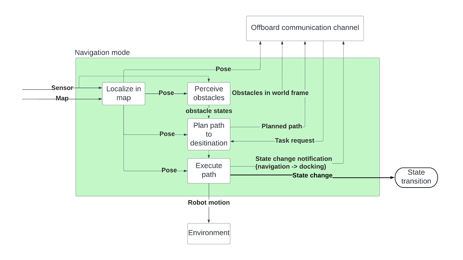
Navigation Mode:
The AMR receives a task request in the form of a start and destination location given in the form of a global map from the Server. The AMR then uses this global map to localize itself based on LIDAR sensor data, identifies obstacles, and plans a local path around obstacles. This allows it to move through a cluttered environment and reach the destination as per the task request.
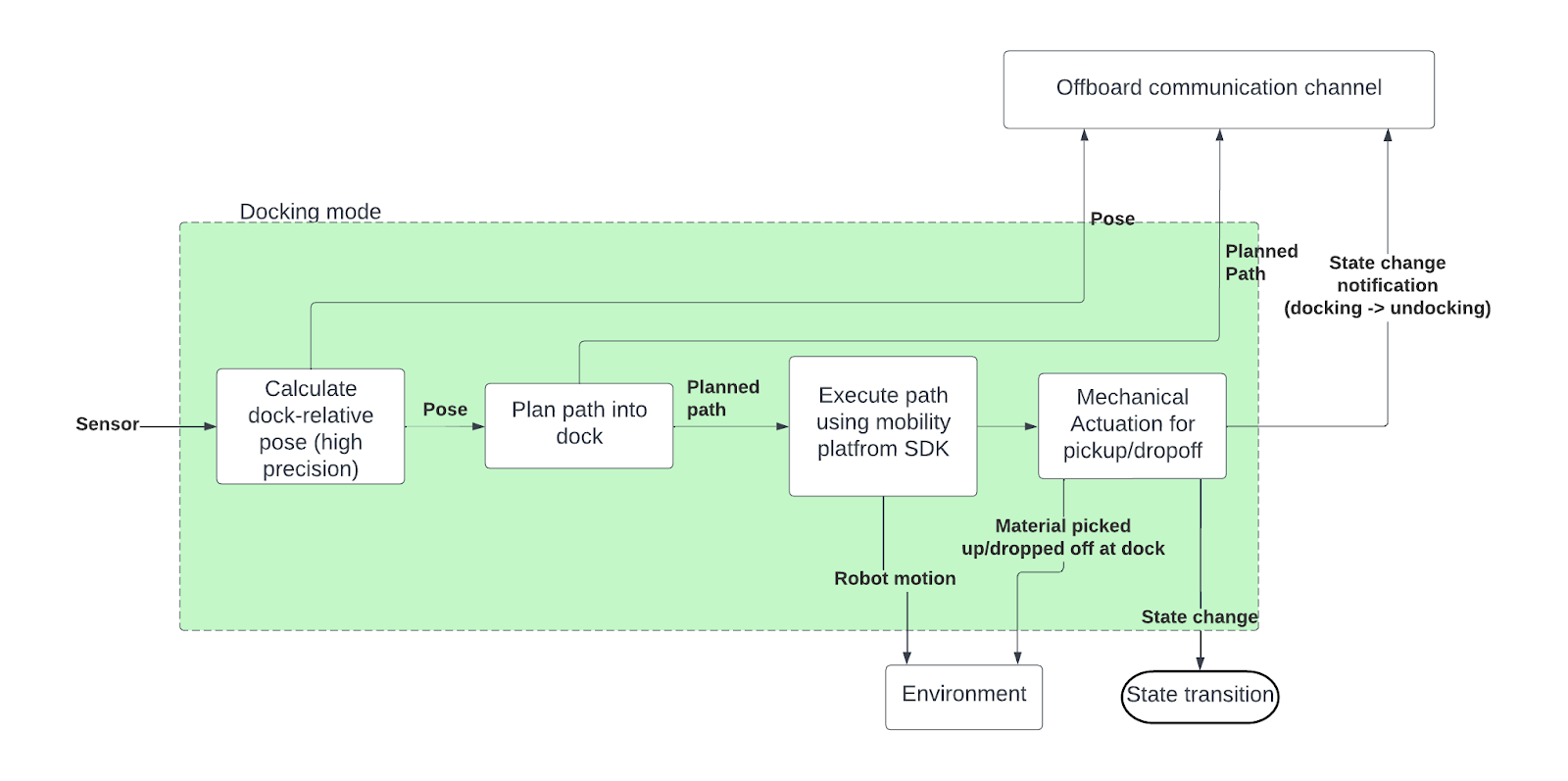
Docking Mode:
Undocking Mode:
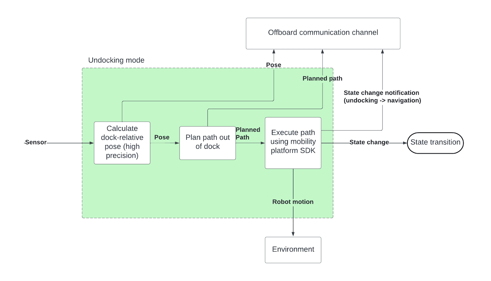
The docking and undocking modes have similar functions, with the exception that there is no mechanical actuation in the undocking mode. In both modes, the localization is relative to the dock (pure vision-based, no pre-built LIDAR map) and path planning is fine-grained to ensure that the AMR aligns well with the dock.
Cyber-physical Architecture
The figures below show the Cyber-Physical Architecture of the” Autonomous Material Handling for MFI’s Lego Testbed” System. The diagrams below are split into two subsystems – the offboard and the onboard subsystem. Together they include the major software and hardware components as well as the flow of information, energy, and material. The diagrams closely mirror the functional architecture (from section 4) with the addition of a power management system block to the onboard subsystem. The full cyberphysical diagram can be found here.
5.1 Offboard Subsystem:
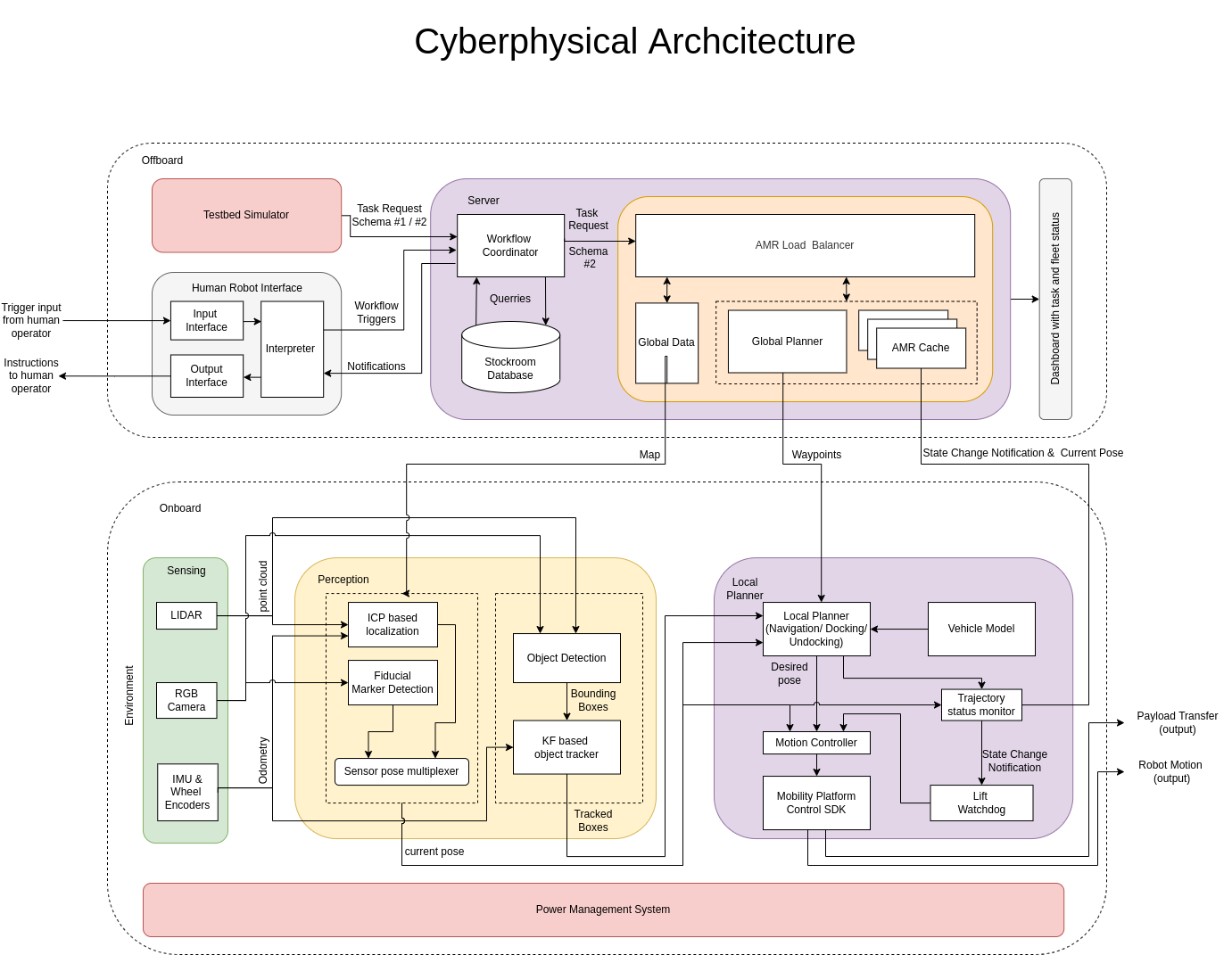
Figure 5.1 Offboard Cyberphysical Sub-system
The offboard subsystem consists of a server, a testbed simulator, and the Human-Robot Interface.
The testbed simulator module is a placeholder for the actual LEGO testbed which will serve as the customer for our system by sending task requests. These task requests will contain information such as the number of lego bricks required, and the color of the desired lego bricks. the target location.
The Human Robot Interface (HRI) will be used to take user inputs and initiate workflow triggers. The HRI allows asynchronous communication between humans at different points in the workflow.
The server comprises a workflow coordinator and a fleet management system. The workflow coordinator handles workflows between the testbeds, HRIs, the stockroom, and the Autonomous Mobile Robots (AMRs). The workflow coordinator communicates the task request to the fleet management layer which has a load balancer, a global data cache, a global path planner, and caches to store the states of the AMRs. The Fleet Management System (FMS) – Balances the load between the AMR. Additionally, the server also handles communications between the system and the user.
After computing the best AMR to service the request the server plans a global path and sends this information to the AMR sub-system.
The high-level states the AMRs go through in order to achieve the payload transfer are – the navigation mode, the docking mode, and the undocking mode.
5.2 Onboard Subsystem:
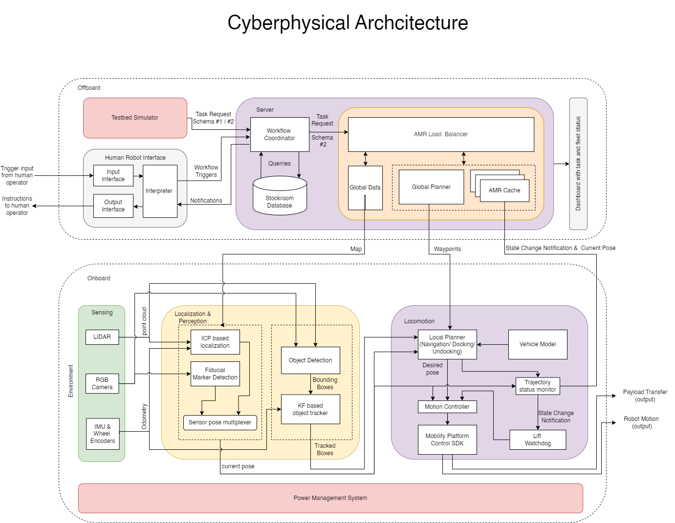
The onboard subsystem comprises a sensing block, a perception block, a local planner, and a power management system.
The sensing block houses the LIDAR and RGB camera and an IMU. These sensors provide the depth information and the visual information necessary for the AMR to navigate in the testbed environment. The sensor suite does not contain a GPS because the environment in which the system is aimed at being deployed is on the factory floor which is an indoor environment and is a GPS-denied environment.
The perception block performs iterative closest point-based localization using the point clouds generated by the LIDAR and a precomputed map of the environment. In addition, the block also performs fiducial marker-based pose estimation using the RGB data. The pose estimates from these two blocks are multiplexed by a sensor pose multiplexer block which gives the current pose depending on the data available and the state of the system. The LiDAR and RGB camera data is then used for object detection and tracking for real-time obstacle avoidance.
The locomotion block – the current pose estimates and the information of the detected objects are propagated to a local planner which generates the desired pose of the AMR which is then given as input to a motion controller. The motion controller is a modular block designed in such a way that the base-level control algorithm can be swapped without affecting the architecture or logical flow of the other blocks. The motion controller takes in the current pose from the perception block and the desired pose from the local planner as input and gives a control output to the mobility platform using the APIs exposed by the mobility platform SDK. This block also houses a trajectory status monitor which triggers state change notifications and the docking undocking process. The overall output of this block is the desired payload transfer and robot motion.
The power management system block routes the power to the entire AMR subsystem which includes the power to the onboard computer, the sensing system, and the actuators.
System Design description/depiction
Based on the cyberphysical architecture described above, we have broken down the system into the following components, each of which will be independently verified/validated:
Testbed Simulator
The role of the testbed simulator is to provide structured inputs in the form of task requests to the server. The task requests can further be classified into two schemas – Schema#1 and Schema#2. A task request with schema#1 will contain the number of lego bricks, the color of the lego bricks, the start location, and the destination location. Whereas, a task request with schema#2 will only contain the start location and destination location. The testbed simulator initiates this cycle by sending a task request using one of the two schemas discussed.
Human-Robot Interface (HRI)
This subsystem is physically located at the work cells, kitting stations, and stock rooms to facilitate interactions between the AMR and the human operators. Specifically, the HRI will give clear instructions on the type and quantity of parts that the AMR requires to complete its task.
Server
The server performs several functions including balancing workload amongst the AMRs, monitoring and maintaining the inventory, planning global AMR paths, and interfacing with the frontend HRI and Dashboard modules.
The AMRs receive pre-built maps for localization, and waypoints of the global plan and also transmit their own status (pose and state) to this server.
The Workflow coordinator – handles all the workflow triggers from the HRI, testbed simulator blocks, and the stockroom and gives a single broken-down input to the fleet management system.
The fleet management system (FMS) is located on the central server. The FMS communicates with the AMRs and monitors their status and sends updates of real-time states and task states of the AMRs to a user dashboard. The fleet management layer also encompasses a load balancing block that assigns a given task to the best AMR available by taking into account different factors such as battery level, estimated time of completion of the task, the distance of the AMR from the stock room, etc. After selecting an AMR to complete a task. The FMS then sends the start location and the destination location of the AMR to a global planner which computes an optimal path using A* taking static obstacles into account. This is a coarse plan which is reiterated by a local planner over a shorter horizon in order to avoid dynamic obstacles. Finally, a request with start and destination locations with waypoints, and a global map is sent to the AMR for it to service the request. If an AMR is lost or added, this information will be relayed to the rest of the system through the FMS.
Sensing
The sensing block incorporates LIDARs, RGB cameras, and sensors such as IMUs to find robot pose. The LIDAR point clouds are used for localization and obstacle avoidance in downstream modules. The RGB camera is primarily used for docking and undocking modes for dock-relative localization using fiducial markers.
Localization & Perception
The localization & perception subsystem consists of a localization and an object tracking module. The localization module in the navigation mode uses point clouds from the LIDAR sensor as well as a global pre-built map provided by the server to localize using ICP (Iterative Closest Point). In the docking/undocking modes, the localization module uses RGB images of fiducial markers to calculate the robot pose relative to the dock. The multiplexer combines the two data streams and ensures that downstream blocks always receive robot pose.
The object tracking module performs object detection in both LIDAR point clouds as well as RGB images. These objects detected by the camera and LIDAR are then tracked using a Kalman Filter with the help of IMU and Wheel encoder readings. Tracking objects allows the AMR to judge whether the object is static or dynamic (mostly humans or another AMR) and accordingly take action to wait for the obstacle to pass or plan a path around stationary objects.
Locomotion
The local planner is used for planning over a short horizon in order to accommodate dynamic changes in environments such as moving obstacles. The local planner takes in the AMRs current pose, obstacle information, and the global plan from the server as input. In case of no obstacles, the local planner generates the desired pose which will keep the AMR on the trajectory generated by the global planner. However, if any dynamic obstacles are encountered the local planner will plan around this obstacle and send an alert to the server to reflect the same on the dashboard. The output of the local planner is the desired pose that is given to a motion controller.
The motion controller is a modular block that can be swapped out for different controllers such as PID, LQR, and MPC. The motion controller takes in the desired state and current state as input and generates a control output which is then passed to the mobility platform for the motors to be actuated and result in the desired motion.
A trajectory status monitor and a lift watchdog run parallelly with the motion controller to monitor the progress of the AMR and generate workflow triggers and send alerts back to the server. The lift watchdog is used to generate a trigger for the lift actuation after the AMR is docked/ undocked.
Power Management System
The power management system block routes the power from the onboard battery to the entire AMR subsystem which includes the power to the onboard computer, the sensing system, and the actuators. The main role of the power management block is to convert the 24V 6A input to 12V 4A and 12V 2A.