Mobile Platform
The mobility subsystem forms the structural chassis and movement apparatus of the robot, which was entirely built from scratch. It moves along the rails of the drip pan which is ordinarily used by Koppers factory equipment to move wood ties. In its current state, the mobility platform achieved its intended goals for SVD which was to move at least .17 m/s (the platform achieved .2m/s) and stop at the end of the testbed.
The chassis came together as the result of months of mechanical design. The chassis is primarily composed of aluminum 80/20 extrusions, an eighth inch aluminum sheet to make a bottom enclosure, aluminum railroad-style wheels, a linear actuator rail, a stepper motor and drivetrain, IR sensors (or time-of-flight sensors), and assorted electronics.
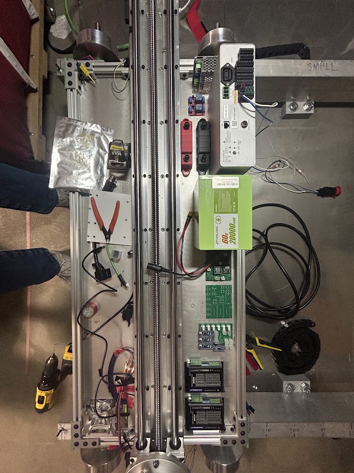
Mobile platform photographed during mounting of electronics
The linear actuator, which moves the arm across the width of the robot had to be mounted to the chassis. This was done by drilling 16 holes through the aluminum sheet to line up with the mounting holes on the linear actuator.
For the drivetrain, one axle is driven by an electric motor, while the other axle spins passively. The driven axle is controlled by a Nema 23 stepper attached to a 7.5:1 worm gearbox that is mounted to the side of the chassis. A special design was required to prevent the axles from sliding out of place. Guards are attached around the axles and mounted to the chassis so that they can press against thrust bearings wrapped around the axles. A dedicated Arduino is used to control the stepper motor. The Arduino sends signals to the stepper motor driver to accelerate to 0.17 m/s and decelerate to stop.
The four IR sensors are placed on the corners of the platform and face downwards at slight angle off the normal. The IR sensors detect when a “cliff”, or end of the pan, has been reached. They are also there to detect the blocks that structurally support the rails. Cliffs are detected when the sensor reading goes above a 250mm threshold. In the graph you can see that the cliff is at roughly 280mm. Similarly, blocks can be detected when the IR sensor falls to around 150mm then rises again to around 210mm. The IR sensor is connected to a different dedicated Arduino than the Arduino used for the drivetrain. This Arduino reads the sensor output at roughly 6 hertz, which is first filtered by the sensor hardware. Once a cliff is detected this Arduino sends a signal to the drivetrain Arduino to stop immediately.
Cleaner Manipulator
The cleaning manipulator subsystem is a robotic arm tasked with providing the motion and force needed for clearing creosote off the drip pan. The end effector of the manipulator is the cleaning tool. There are three main functions this subsystem performs:
- Position the camera to view the drip pan surface before cleaning
- Plan collision-free trajectories for pushing and pulling the creosote towards the drain of the drip pan.
- Move the cleaning tool along the calculated cleaning trajectory while maintaining normal force for cleaning.
- Periodically use a self-cleaning block to remove built-up creosote from the squeegee.
To accomplish these tasks, we use a 2-meter-long linear actuator combined with a 6-degree-of-freedom robotic arm. The linear actuator is used to move the arm from one end of the robot to the other. This allows the arm to reach, and thus clean, the entire width of the pan. For our purposes, we use the UFactory 850 arm.
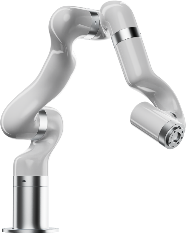
UFactory 850 robotic arm
Cleaning Tool
The cleaning tool was designed around a Viton strip squeegee, which proved to be the best material we found when it came to pushing creosote, which is the main skill needed in order to fulfill requirement PM 5.2. The cleaning tool also has springs and a load cell, which allow for consistent force application. The mount section was designed to be attached to the UFactory arm and to the camera that will be used by the system. However, after lots of consideration and testing the tool, we arrived at a final version which is depicted below.
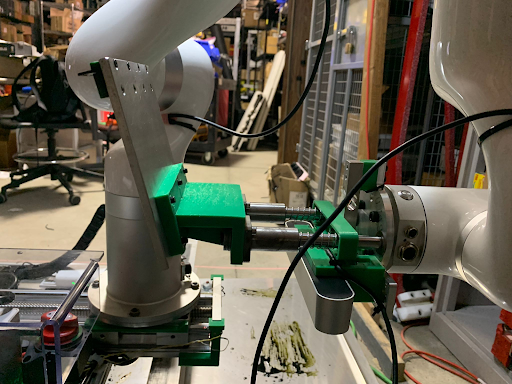
Cleaning Tool
Perception/Computing
In order to test the accuracy of our perception system, datasets of factory and testbed images were prepared by creating annotated ground truth images. Annotations depict the class which each pixel belongs to. The classes are creosote (full creosote coverage), semi-creosote (a thin layer of creosote which appears bronze colored), and clean (no creosote). One thing to notice is that the annotation is subjective to the annotator, an this fact is reflected in the fact that the distinction between classes can be ambiguous and discretionary in many cases.
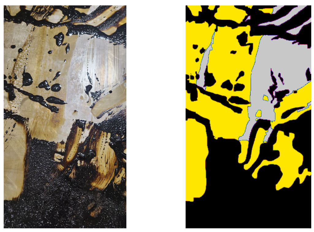
Hand annotation of the ground truth for test images: (Left) the original image and (Right) the corresponding ground truth annotation.
After the segmentation algorithm gives masks for each class for an input image, the confusion matrix is determine against the ground truth for each class. This matrix is eventually used to determine the accuracy for each class – creosote, semi-creosote and clean regions.
The above explained methodology works well on the obtained factory images – where the lighting conditions are uniform and favorable, however, the testbed we demonstrate the system on suffers from extensive shadows and lighting variations, as well as glare. Thus, we deemed a data based approach to be more robust. We collected and annotated the corresponding testbed data, for creosote instances and trained a YoloV8 model to work on the same.
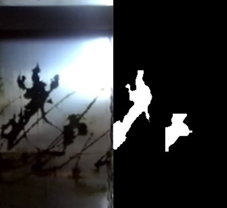
YoloV8 Segmentation: (Left) Input and the corresponding (Right) Segmentation Output
User Interface
The user interface subsystem comes from the project requirement that the system needs to update the user promptly. The developed interface uses a custom Foxglove layout, and is effectively able to convey important system information, in real-time including the sensor inputs, cleaning progress and success rate, the battery level, as well as provides a venue to pass start/stop commands to the robot and home the robot.
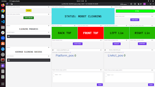
The User Interface
In order to meet our requirement of having responsive remote control of the robot, we use a wireless bridge which effectively connects two LAN’s together. The LAN on the robot, and a set of remote computers used for monitoring. On this network of remote computers, any one of them can run the user interface via a web browser. Additionally, these computers can be used to SSH into the robot’s on-board computer to make changes, run scripts, and launch ROS2 nodes. The robot arm can also be controlled remotely using UFactory’s built-in web interface.