
Mapping
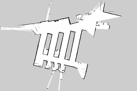
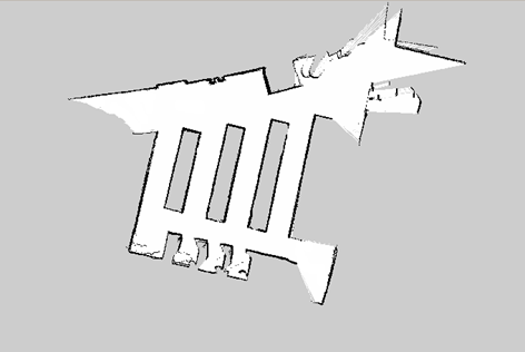
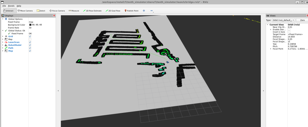
Implement a collision-free map converter that takes the built occupancy grid map from slam_toolbox as input. It generates an occupancy grid cost map to avoid possible obstacle collision in the mission planning process. It also labels the map grid outside the drivable area for the user interface so that waypoints are added correctly in the interface.


Path Planning Algorithm
Map Inflator
Motivation:
Instead of relying on Nav2 as done previously in the map_converter module, we aimed to implement a custom map inflation method. This approach removes the need to launch multiple redundant Nav2 nodes and allows tighter integration with our custom planning pipeline.
Methodology:
This work introduces a map_inflator ROS 2 node that inflates obstacles in an OccupancyGrid to improve navigation safety. The node expands occupied cells to create a buffer zone that accounts for the robot’s physical footprint, ensuring the global planner maintains safe clearance from obstacles and walls.
Key Features
Obstacle Inflation: Transforms a standard occupancy grid into a “cost map” where obstacles are thickened based on a configurable radius in meters.
Configurable Safety Buffer: Uses the inflation_radius_m parameter to automatically calculate the required number of grid cells based on the map’s resolution.
Customizable Thresholds: Allows users to define what constitutes an “occupied” cell and toggle whether unknown territory (v < 0) should be treated as a lethal obstacle.
| Topic | Type | Description |
|---|---|---|
| /map | nav_msgs/msg/OccupancyGrid | Input: The raw static map from a map server or SLAM node. |
| /cost_map | nav_msgs/msg/OccupancyGrid | Output: Current robot state from Localization (Particle Filter). |
Path Planning:
Motivation:
Methodology:
Key Features:
| Topic | Type | Description |
|---|---|---|
| /map | nav_msgs/msg/OccupancyGrid | Input: The raw static map from a map server or SLAM node. |
| /cost_map | nav_msgs/msg/OccupancyGrid | Output: Current robot state from Localization (Particle Filter). |
Smoothing
Motivation:
Methodology:
Key Features:
| Topic | Type | Description |
|---|---|---|
| /map | nav_msgs/msg/OccupancyGrid | Input: The raw static map from a map server or SLAM node. |
| /cost_map | nav_msgs/msg/OccupancyGrid | Output: Current robot state from Localization (Particle Filter). |
- Replaced the initial brute-force search (O(n!)) which was computationally
- prohibitive for n > 10.
- o Implemented a bitmasking approach to optimize the storage of the DP table,
- reducing time complexity to O(n^2 2^n).
- o Result: Capable of finding the mathematically optimal tour for small-to-medium
- waypoint sets.
Held-Karp Algorithm (Dynamic Programming)
Nearest Neighbor (Greedy Heuristic):
- o Implemented as a fallback for high-density waypoint scenarios (n > 20).
- o Utilizes Dijkstra’s algorithm for cost estimation between nodes.
- o Result: Provides rapid solutions with minimal memory overhead, ensuring
- system responsiveness when optimality is secondary to speed.
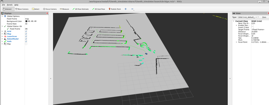
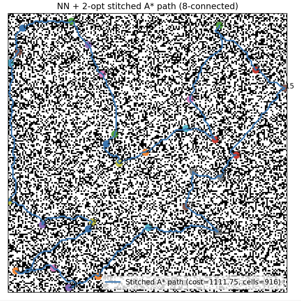
Implemented one-to-all Dijkstra from the start to compute true grid-based travel costs to every target waypoint. And ensures costs reflect feasible paths around static obstacles, rather than relying on Euclidean distance.
● Built a TSP solver for waypoint ordering, which use Nearest neighbor as the first stage as an initial greedy tour, then apply 2-opt (swap edges) refinement to reduce crossings and lower total cost iteratively
● After determining the waypoint visiting order, used Hybrid A* to generate the
kinematically feasible path connecting the ordered waypoints.
● Packaged the Python implementation into a ROS2 package: path_planning

Local Planning (Pure Pursuit)
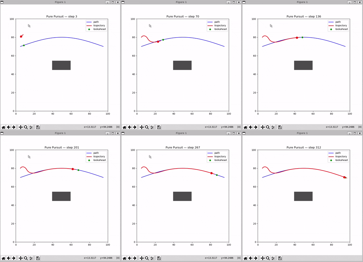
Implemented a pure-pursuit local planning module that takes the planned path and current vehicle state as input, computes a steering command, and publishes it to the vehicle control module. This enables the robot to follow smooth trajectories generated by the planning unit.
Pure Pursuit Algorithm:
Bicycle Model Integration:
| Topic | Type | Description |
|---|---|---|
/planning/path | nav_msgs/Path | Input: Sequence of waypoints from the Planning unit. |
/pf/pose/odom | nav_msgs/Odometry | Input: Current robot state from Localization (Particle Filter). |
/drive | ackermann_msgs/AckermannDriveStamped | Output: Target steering angle and velocity for the vehicle. |
UI/UX
Implemented a web-based user interface to visualize the map and robot pose, manage waypoints (add/drag/delete), publish missions, and render subscribed paths on the map.

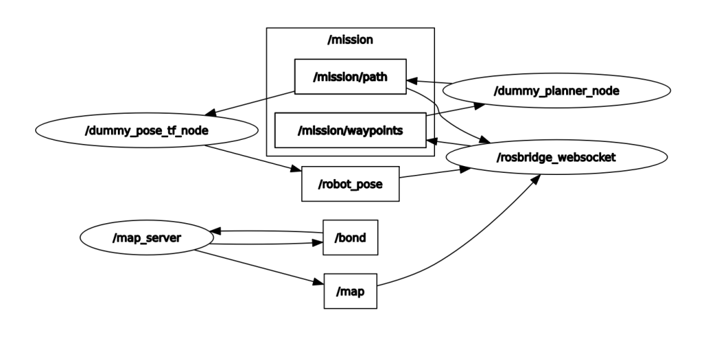
After the robot is launched, start the frontend application and open it in a browser. The application subscribes to the map and robot position from ROS2 topics and renders them in the interface. Users can click directly on the map to create new waypoints or drag existing waypoints to modify their positions. In delete mode, users can click an existing waypoint to remove it (a button will be provided to switch between waypoint editing modes). Once all mission waypoints are set, users can click a button to publish them back to ROS2 as a PoseArray topic. The planner node then generates a path topic as expected, which the application subscribes to and renders in the interface.