
Overview
Since the Knightscope platform’s power system is vendor-provided and not modifiable, we do not anticipate the need to design a dedicated PCB specifically for that platform. Instead, we propose the design of a standalone power module aligned with our learning objectives and prior laboratory experience. During the Sensors and Motors Control Lab, both a 12V DC motor and a 12V stepper motor were powered from a shared 12V supply. These actuators exhibited different electrical characteristics:
- DC motors draw moderate nominal current but may experience high startup and stall currents.
- Stepper motors, driven by current-controlled drivers, draw sustained current with transient peaks.
In a shared unprotected supply configuration, a short circuit or overcurrent condition in one subsystem may propagate and disable the entire system. To address this issue and support safe subsystem integration and prototyping, we propose the design of a protected 12V Power Distribution Board (PDB). The board provides:
- Three independently protected 12V output channels
- Per-channel overcurrent protection
- Visual status indicators
- Test points for diagnostics
- Input-level protection against reverse polarity and overcurrent
This design serves as a safe 12V power hub suitable for laboratory subsystem testing and actuator integration.
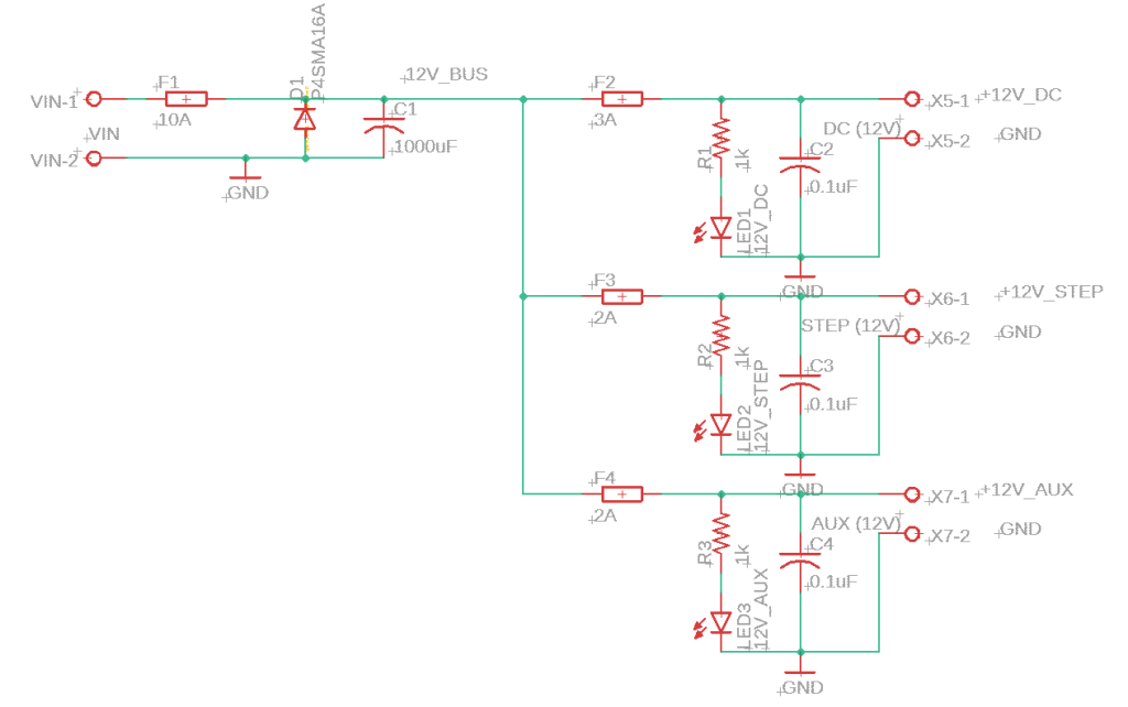
Schematic
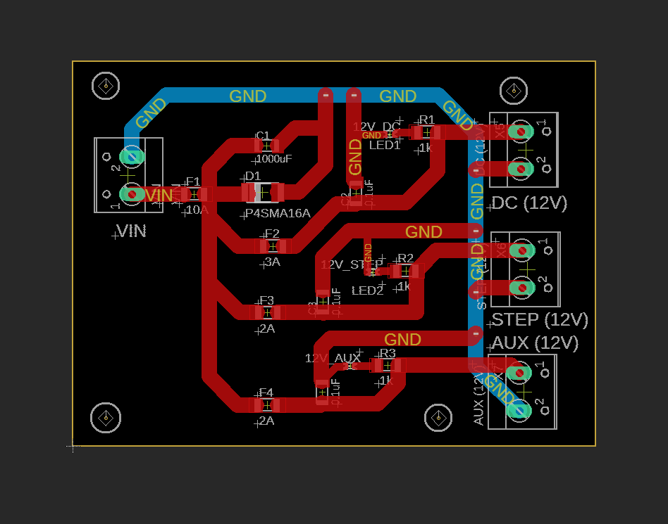
Board Layout
Distribution Architecture
The proposed PCB consists of:
- One 12V input connector
- Three independent output connectors
- Per-channel resettable polyfuse
- Per-channel LED indicator
- VIN and output test points
This architecture ensures:
- Fault isolation between subsystems
- Prevention of cascading shutdowns
- Safe actuator bring-up and debugging
No voltage regulation is required for this design, as all targeted subsystems operate directly from the 12V bus. The board does not implement H-bridges, MOSFET switching stages, or active power control. Motor control is handled by external driver modules. This PCB focuses solely on protected power distribution.