
Skeleton Detection
Summary
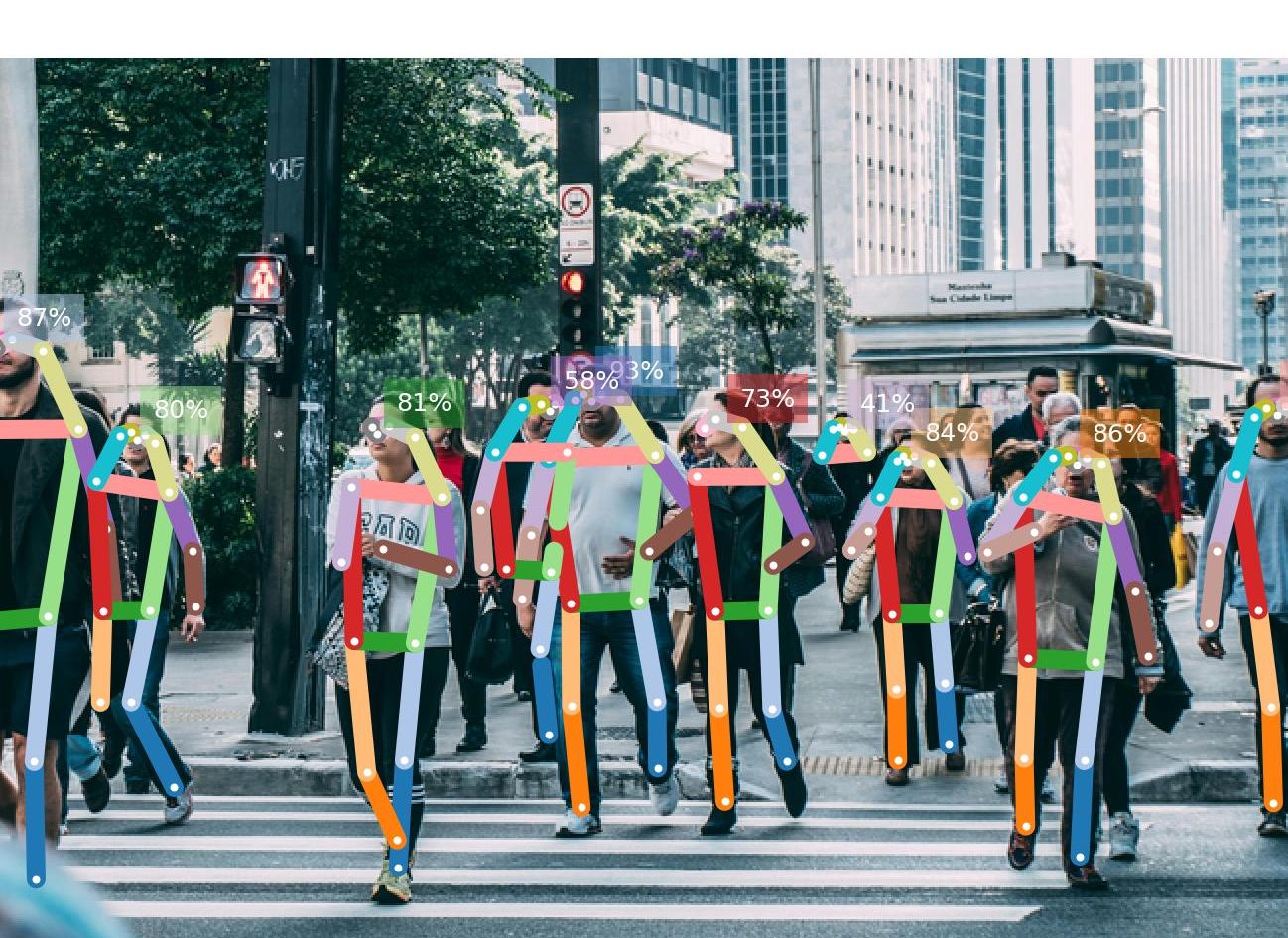
Skeleton Detection is a ROS 2 perception module under ICM (Intelligence Control Module) that adds human pose understanding to the anomaly detection pipeline. Built on OpenPifPaf, it processes image streams from either prerecorded MP4 footage or a live Intel RealSense D435i camera, detects human skeleton keypoints, and tracks individuals across frames using IOU-based identity matching. The system publishes structured skeleton metadata for downstream use, generates annotated image output for visualization, and can save both an annotated video and a JSON log for offline review and logging. This makes the module useful both for real-time monitoring and for analyzing recorded scenes during development and testing.
Data flow
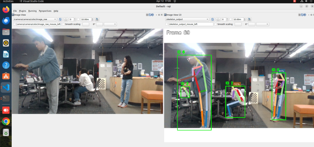
In offline mode, a local MP4 is used as the input source. The frames are routed through the camera reader path and published to the detector input topic, typically /dummy_camera/image_raw. The skeleton_detection_node subscribes to that image stream, runs skeleton inference and tracking, then publishes structured skeleton metadata on /skeleton_detection/frame and annotated images on /skeleton_output. When enabled, it also saves an annotated MP4 and JSON metadata log to disk.
In live mode, the Intel RealSense D435i provides the input image stream through the ROS camera topic, typically /camera/camera/color/image_raw. The skeleton_detection_node subscribes directly to that live topic, processes each incoming frame, publishes skeleton metadata and annotated image output, and can also export the same disk artifacts for later analysis.
| Topic | Type | Description |
|---|---|---|
| /camera/camera/color/image_raw | sensor_msgs/msg/Image | Input: Live RGB image stream from the Intel RealSense D435i camera. Used in live detection mode. |
| /dummy_camera/image_raw | sensor_msgs/msg/Image | Input: Image topic consumed by skeleton_detection_node in the offline/MP4 workflow. It serves as the detector input topic when frames are routed through the camera reader path. |
| /skeleton_detection/frame | skeleton_detection/msg/SkeletonFrame | Output: Per-frame skeleton metadata, including detected people, joint data, bounding boxes, tracking IDs, and timestamps. |
| /skeleton_output | sensor_msgs/msg/Image | Output: Annotated image stream with skeleton overlays, bounding boxes, and tracking IDs drawn on each frame. |
Anomaly Detection
The Anomaly Action Detection Module is a two-stage safety sub-system integrated into the autonomous driving platform via ROS 2 (Humble). The pipeline begins with a Graph-Jigsaw Conditioned Diffusion (GJCD) model that processes 17-keypoint COCO skeleton sequences in sliding windows of 24 frames. This first stage operates downstream of existing skeleton detection nodes, calculating a normalized reconstruction error to identify potential anomalies. To optimize computational efficiency, the system only triggers the second stage, a pre-trained LLM BART-large-mnli, when the initial anomaly score exceeds a configurable threshold, ensuring high-performance processing without unnecessary overhead.
For final classification, the module translates complex motion dynamics, such as joint velocity and spatial displacement, into natural language descriptions for the LLM. The LLaMA 3 model then categorizes the behavior into specific labels such as fighting, loitering, or chasing, providing both an anomaly score and a human-readable explanation.The final fused output is delivered through a structured ROS 2 JSON topic, supporting seamless modular integration and real-time operator alerts.
Key Features:
| Topic | Type | Description |
|---|---|---|
| /skeleton_detection/frame | skeleton_detection/msg/SkeletonFrame | Input: The skeleton detection result. |
| /anomaly_detections | std_msgs/msg/String | Output: Anomaly action detected with time frame and person id. |
Mapping
Migrate the mapping technique from the F1TENTH stack to the LSV simulation environment to support future patrol robot autonomy development. This task focuses on mapping and map processing so that the LSV robot performance can be validated.
Key Features:
- Obtain recorded rosbag file with mapping and localization topics.
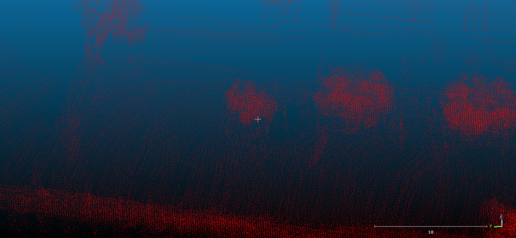
- Operate LIO-SAM_ROS2-PIXKIT mapping offline and parameter tuning.
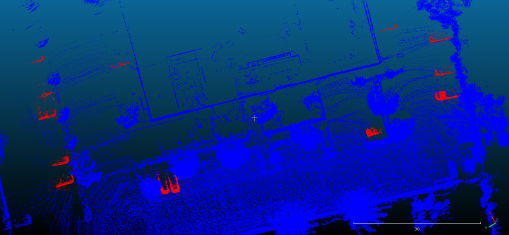
- Use point cloud editing tool (CloudCompare) to remove dynamic objects and outliers.
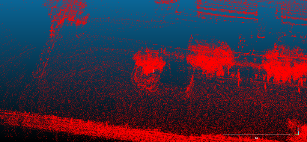
- Down-sample static map by voxelization.
- Use built map to generate corresponding Lanelet map.
Acceptance Criteria:
- Rosbags contain sufficient topics for mapping and localization.
- LIO-SAM mapping correctly constructs environments with no structural misalignment.
- Erase all dynamic points and outliers within the dense map.
- The dense map is down-sampled correctly as a sparse map.
- The coordinates of the point cloud map and Lanelet map are aligned.
| Topic | Type | Description |
|---|---|---|
/sensing/lidar/top/velodyne_points | sensor_msgs::msg::PointCloud2 | Input: LiDAR frames for map construction. |
/sensing/imu/imu_data | sensor_msgs::msg::Imu | Input: IMU frames for motion distortion and IMU Preintegration. |
/sensing/gnss/fixposition/nav_sat_fix | sensor_msgs::msg::NavSatFix | Input: GNSS signals for world coordinate alignment. |

Waypoint Scheduler
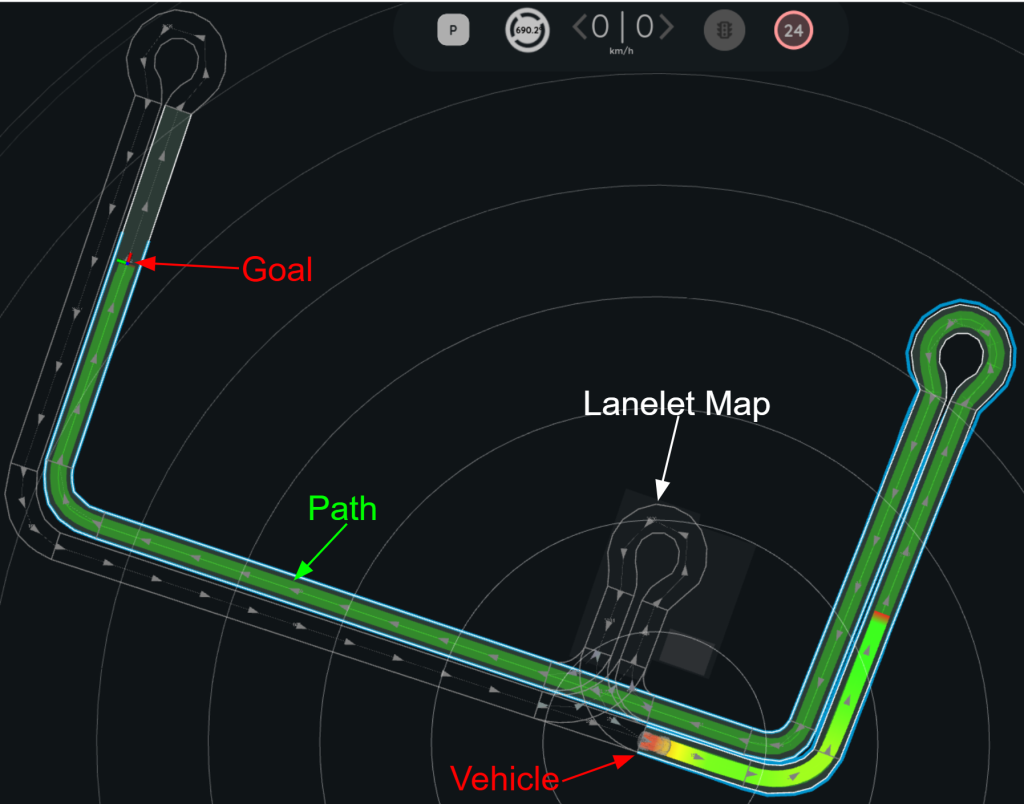
Design a waypoint scheduler and integrate it into the LSV simulation environment to support future patrol robot autonomy development. This task focuses on the scheduler so that the LSV robot performance can be validated.
Key Features:
- Design waypoint scheduler.
- Assign vehicle heading to the pure position waypoint.
Acceptance Criteria:
- Dataflow of waypoint scheduler is correct and work as expected.
- The heading is automatically assigned to the waypoint with the correct direction.
| Topic | Type | Description |
|---|---|---|
/planning/mission_planning/no_heading_goal | geometry_msgs::msg::PoseStamped | Input: Goal point sent from UI with no heading. |
/map/vector_map | autoware_map_msgs::msg::LaneletMapBin | Input: Lanelet map layers with directions. |
/planning/mission_planning/goal | geometry_msgs::msg::PoseStamped | Output: Goal point with heading aligned to closest lanelet map lane. |
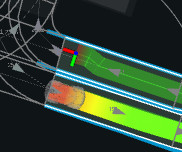
(x,y,yaw) = (-62.8,37.5,0.0)
Output:
(x,y,yaw) = (-62.8,37.5,1.28)
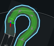
(x,y,yaw) = (-49.2,41.5,0.0)
Output:
(x,y,yaw) = (-49.2,41.5,3.10)
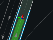
(x,y,yaw) = (-24.7,86.8,0.0)
Output:
(x,y,yaw) = (-24.7,86.8,-0.29)
User Interface
Our user interface is designed to provide intuitive control over waypoints, allowing users to easily add points through clicking, adjust their positions via drag-and-drop, and remove existing waypoints as needed. In addition, the interface visualizes the planned route in real time, along with the robot’s current status and the underlying lanelet map. This integration enables the planner to leverage richer semantic and geometric information for more informed decision-making. Furthermore, based on the lanelet map, the system can compute additional route-related metrics, such as total distance and estimated time of arrival (ETA), offering users a more comprehensive and practical navigation experience.
