System Requirements
Mandatory Performance Requirements
| ID | Requirement | Description |
|---|---|---|
| M.P.1 | First time user inputs map within 15 minutes | GroundsBot should be easy to use |
| M.P.2 | System returns proposed route/coverage map within 5 minutes |
Related to M.P.1, GroundsBot should start up quickly to ease the mind of the user |
| M.P.3 | Cover 1/8 acre in 30 minutes on flat, unobstructed terrain | Minimum performance in ideal conditions |
| M.P.4 | Cut 95% of the grass on flat, unobstructed terrain | GroundsBot provides sufficient coverage of the specified mowing region |
| M.P.5 | Navigate 30 degree sloped, grassy hill | GroundsBot should be able to handle steep slopes safely |
| M.P.6 | Detect 80% of static objects greater than 12 inches in height and 8 inches in width | GroundsBot should be able to recognize static obstacles in order to prevent collisions and mowing accidents |
| M.P.7 | Detect 80% of dynamic objects greater than 24 inches in height and 8 inches in width travelling less than 4 mph | GroundsBot should be able to recognize dynamic obstacles in order to prevent collisions and mowing accidents |
| M.P.8 | Mow to within 3 feet of detected obstacles | GroundsBot should be able to detect an obstacle (M.P.6) and navigate around it to continue its mowing path |
| M.P.9 | Return home to within 5 feet of starting position | GroundsBot should return to its starting position to remove as much hassle from the user as possible |
Desirable Performance Requirements
| ID | Requirement | Description |
|---|---|---|
| D.P.1 | Mow to within 3 inches of a detected obstacles | A stretch goal for when M.P.8 (mow within 3 ft. of obstacles) is achieved |
| D.P.2 | Visually report mowing coverage and obstacles encountered | GroundsBot should report areas it missed so the user knows where to manually mow to achieve full coverage |
| D.P.3 | Deck adjustable 0.5” to 2” | GroundsBot should be able to meet the grass height standards of different golf courses |
Mandatory Non-Functional Requirements
| ID | Requirement | Description |
|---|---|---|
| M.N.1 | Have a functional and easily accessible emergency stop | GroundsBot should be safe to use and easy to shut down in case of emergency |
| M.N.2 | Be clearly visible | GroundsBot should indicate its presence and status to everyone nearby |
| M.N.3 | Do not tear up grass | GroundsBot should not ruin any area it travels over |
Desirable Non-Functional Requirements
| ID | Requirement | Description |
|---|---|---|
| D.N.1 | Operates in low light conditions | GroundsBot should operate in low light conditions to avoid interrupting golfers |
Functional Architecture
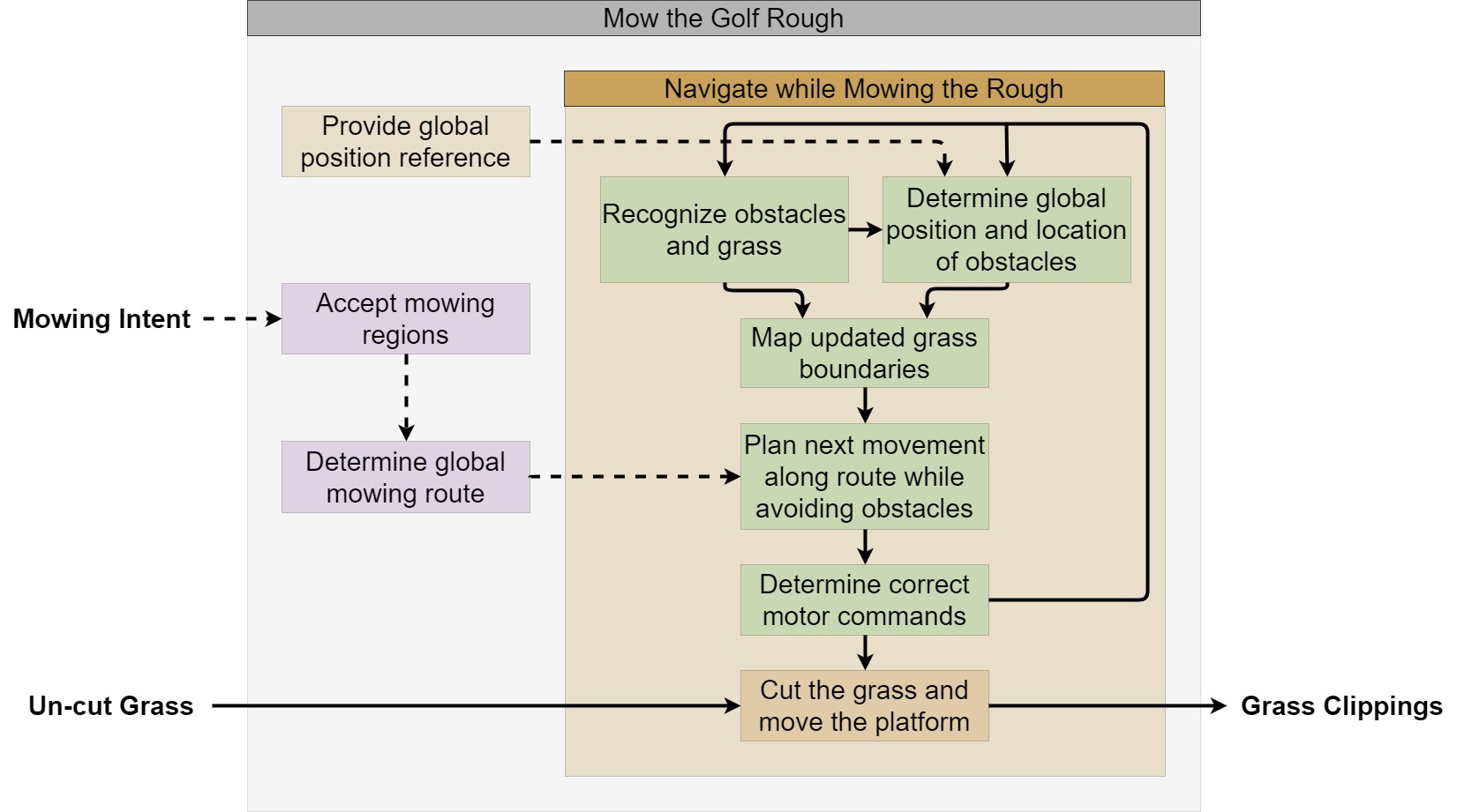
GroundsBot has to perform several key activities in order to produce mowed grass from a given mowing region. The process flow of these activities can be seen below. GroundsBot must receive the intended mowing regions from the user. It must use these mowing regions to generate a mowing plan. From here, the system starts its main mowing loop where it localizes itself and identifies obstacles to generate a map to navigate with. GroundsBot uses this map and the mowing plan to generate a trajectory that avoids obstacles and maximizes coverage. This trajectory is converted to motor commands that are used to move the platform in the right direction to mow grass. The final system comes together to mow the grass in the given mowing region.
Cyberphysical Architecture
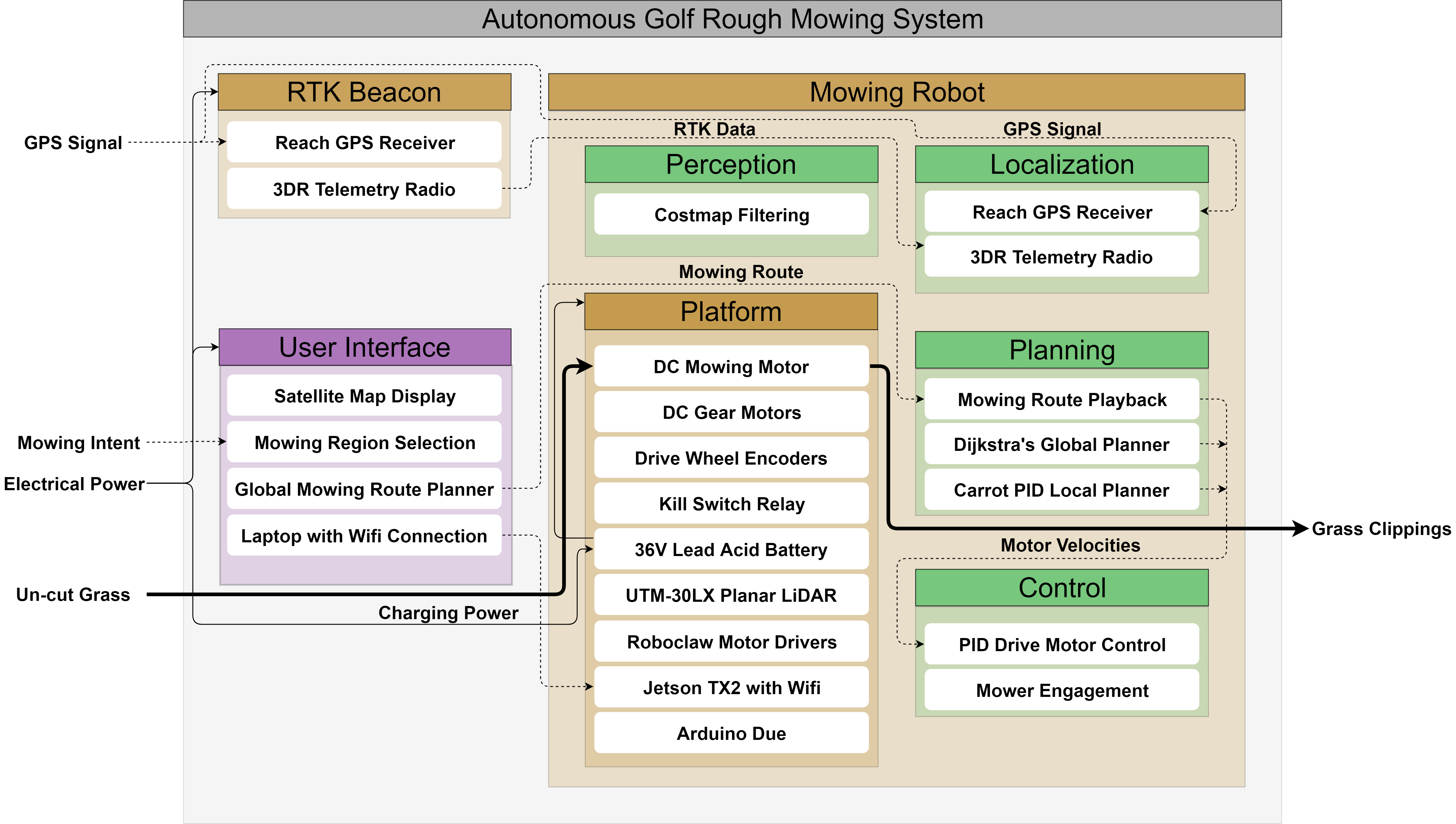
The cyberphysical architecture is shown below. The user interacts with the GroundsBot system through a user-interface that allows them to use a satellite map to select mowing regions. The user-interface connects and uploads the mowing regions to the GroundsBot platform via Wi-Fi. The GroundsBot platform receives the intended mowing region and generates a mowing plan using a coverage planning algorithm.
GroundsBot uses an RTK GPS along with IMU and wheel odometry data to determine its position. To identify obstacles, GroundsBot uses a stereo-camera and surface identification algorithms to build a map of the environment. Using the map and the mowing plan, GroundsBot plans a trajectory to mow the grass using a local motion planning algorithm. The trajectory is converted to motor velocities which are sent to the microcontroller that controls the motor controller. The motors drive the platform and mowing apparatus forward, mowing the grass and covering the mowing region.
System Design Description
GroundsBot is a synergy of mechanical, electrical, and software systems. The system includes a UI for mowing region input, a physical mowing platform for performing mowing and mobility tasks, and a software stack to integrate perception, mapping, and navigation.
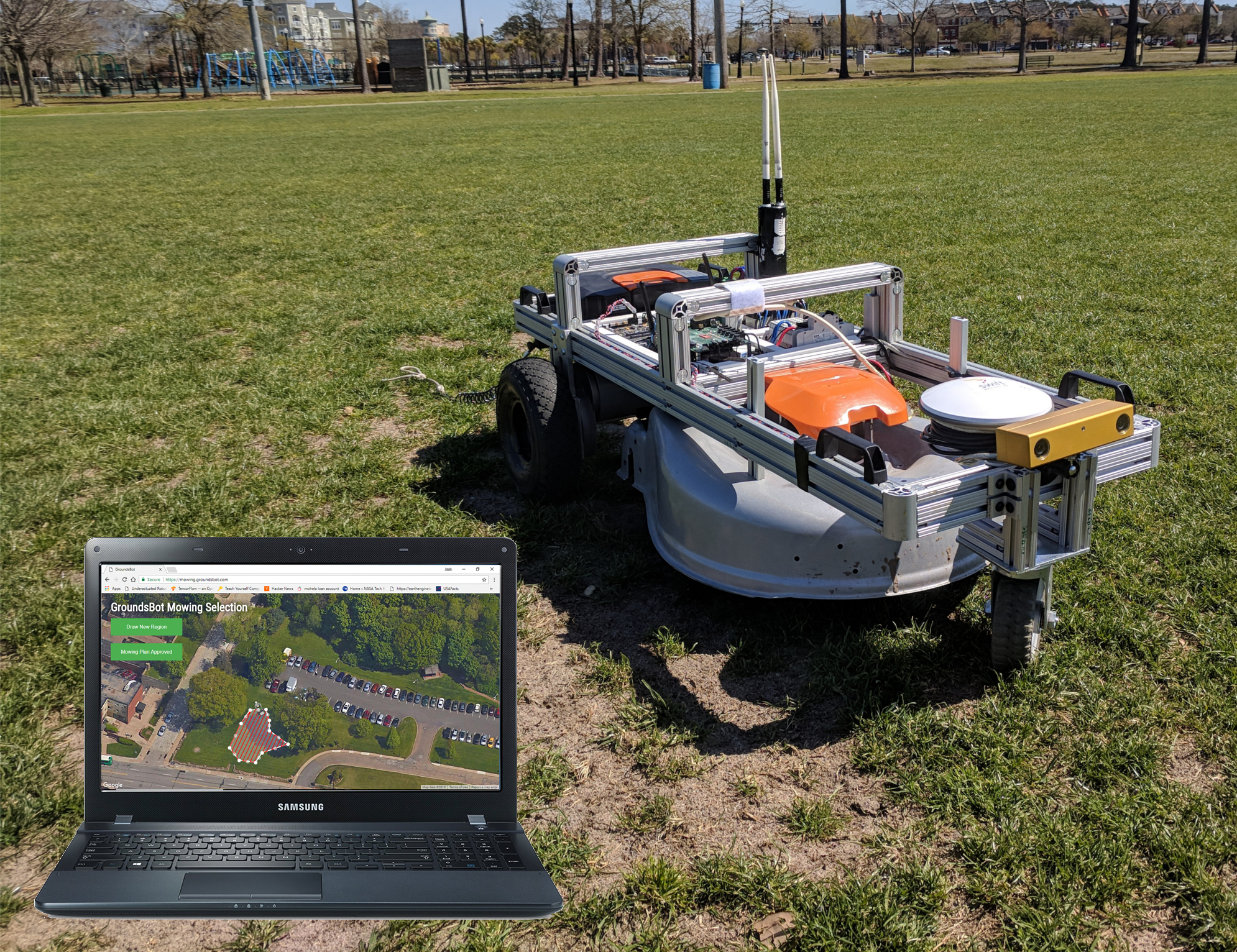
The GroundsBot system deployed for using a laptop to access the UI online.
User Interface
It is critical for the user to communicate a desired mowing path to the robot. This input method must be separate from the robot itself, allowing the user to be somewhere else as the robot mows autonomously.
This input was developed as a web application, accessible through a laptop or mobile device. The website includes a Google Maps interface for selecting mowing regions, and displays the planned mowing route when it is generated. The user interface displays the robot location in real-time and also displays relevant obstacles. The user can choose to draw a completely new region, or modify an existing region by dragging polygon vertices. When a mowing plan is ready to deploy, the user simply approves the mowing plan to activate the robot.
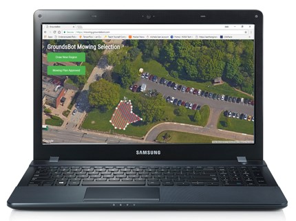
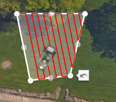
Mowing region input through the user interface, shown in dotted white lines. A planned path for part of this region is shown in red.
Mowing Platform
The mowing platform consists of a differential drive vehicle that carries an off-the-shelf mower. The frame of the vehicle is made mostly from aluminum extrusions. Two motors provided by Discovery Robotics attached to the frame with custom aluminum mounting blocks. 10 inch diameter wheels are used in the rear and a 6 inch diameter caster supports the front. The off-the-shelf mower used is a Worx WG770 cordless electric mower. The mowing deck was removed from this mower and then attached to the carrier vehicle.
The entire system is powered off of the original Worx mower battery. The 36V battery was rewired to provide both a 36V and a 24V output. The 36V output powers the mower blade motor, while the 24V output powers the wheel motors and the other electronics.
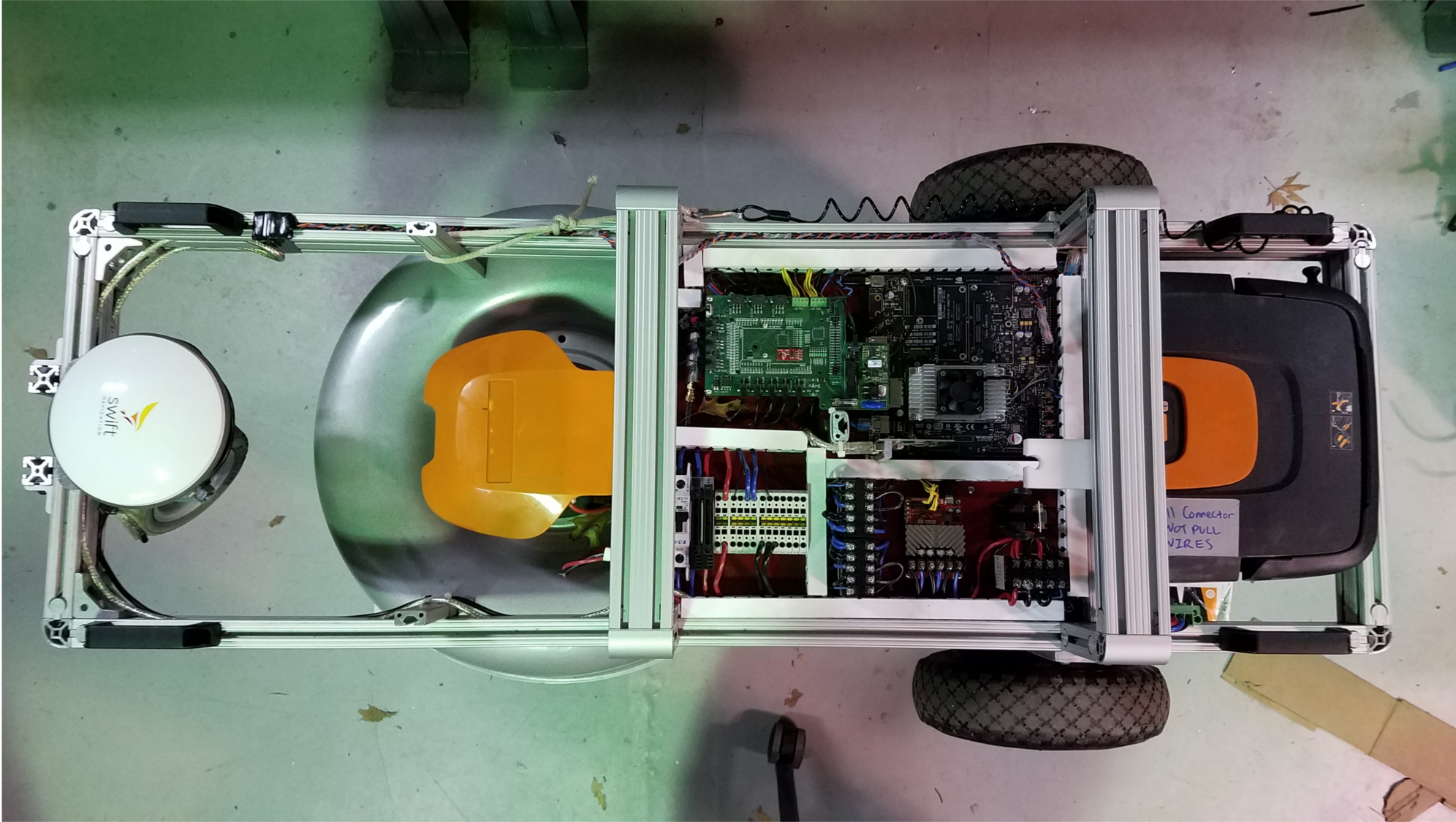
Top view of the mowing platform showing electrical panel, drive system, mowing deck, and GPS.
The differential drive design allows for simple mobility. Steering and forward motion are accomplished with the two motors, reducing points of failure. The battery is placed toward the rear to bring the center of mass closer to the wheels. This balances the platform when driving side-ways on hills while maintaining stability to prevent tipping.
The electrical panel handles power distribution, sensor integration, and motor control. Cabling is routed through duct raceways, preventing wire damage and maintaining easy access for service and re-work.
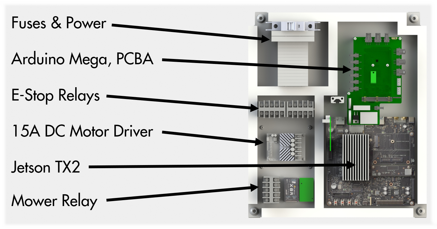
Detailed description of the electrical panel components. Sensor integration is accomplished on the breakout board and power distribution is routed through components mounted on the DIN rail.
A custom PCBA was made to interface the sensors with an Arduino Mega, which serves as the bridge between an Nvidia Jetson TX2 and a Roboclaw motor controller. The Arduino listens for messages coming in from either an RC transmitter or the Jetson, converts the message into a PWM output, and then passes this output along to the motor controller which provides the correct voltages to the motors.
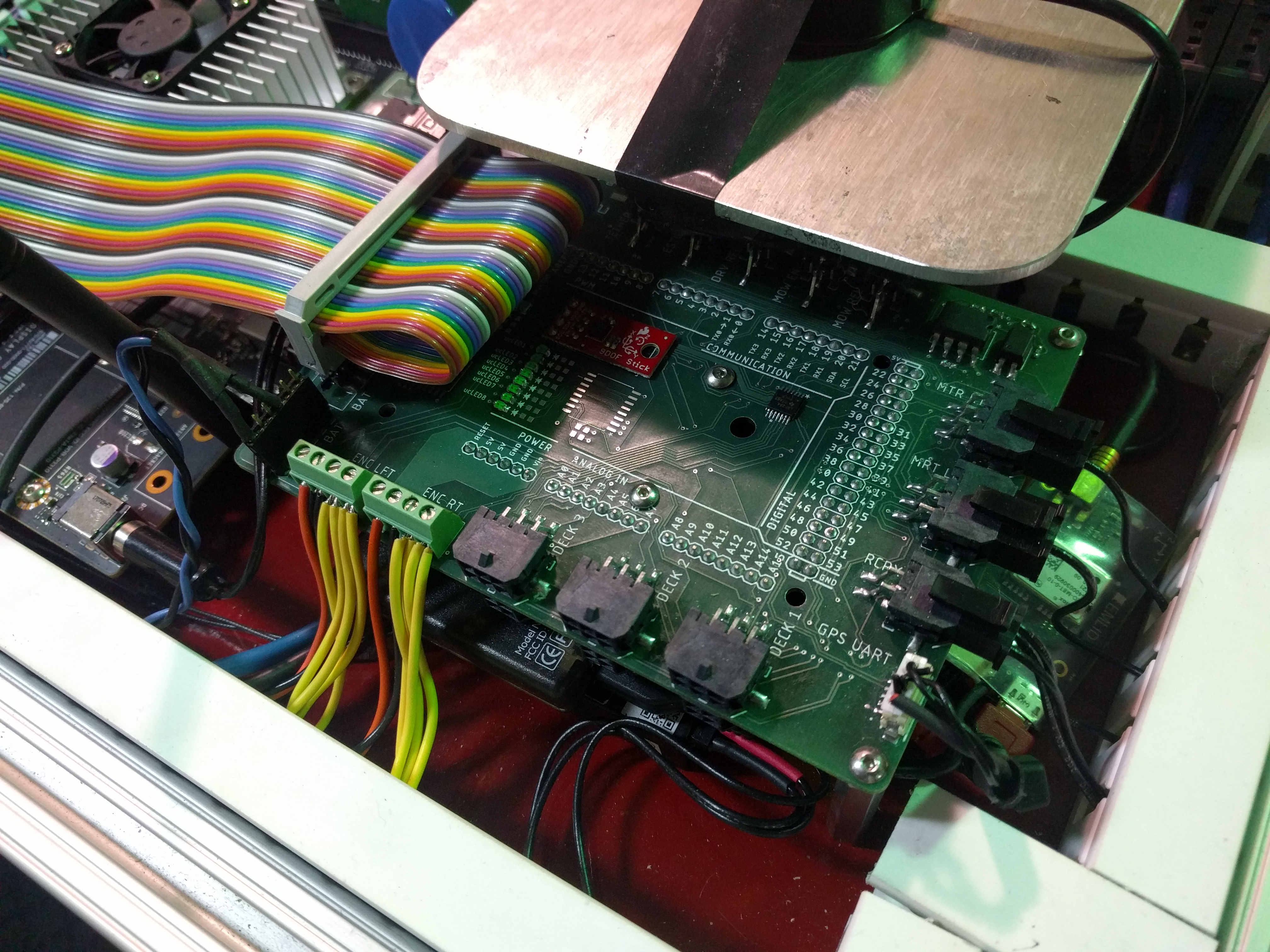
Custom PCBA for power distribution and low level control of GroundsBot.
With regards to safety, a tether was installed on the robot to short the motor connections and brake the motors whenever the tether is pulled. The motors are connected to their power source via relays which shut off when an under-voltage condition is detected, preventing damage to the battery. Fuses are also used throughout the platform to protect components from current surges.
Perception & Mapping
The perception & mapping subsystem is responsible for using lidar scan data to detect obstacles and generate a costmap to be used by the navigation subsystem.
Obstacle detection starts with a laser scan from the Hokuyo UTM-30LX lidar. This planar lidar generates a 180 degree laser scan that identifies the distance to any obstacle seen. The laser scan is filtered using a median filter to reduce the amount noise in the scan. The laser scan is read in by ROS navstack’s costmap2d node. This node populates a costmap of obstacles from the laser scan. The costmap is then used by the navigation subsystem to generate a plan to avoids obstacles.
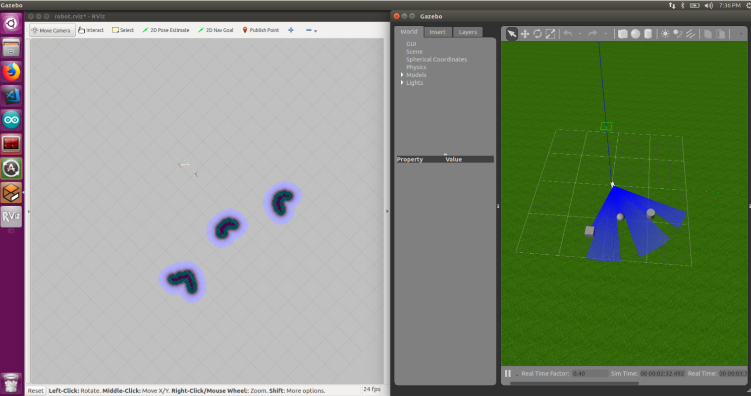
Costmap generated by the filter node on the left from simulated obstacles on the right. One can see the high-cost areas in black that represent the obstacles seen.
Navigation
The navigation subsystem receives a coverage area and sensor input, then sends commands to the motors to ensure GroundsBot covers the entire input area. This task can be split into five key activities: localization, coverage planning, waypoint serving, global planning, and local planning. These activities are separated into ROS nodes that work together to make up the complete Navigation subsystem. Let’s take a dive into each activity to learn the specifics of how they work.
The localization node reads in data from the IMU, RTK GPS, and wheel odometry, then uses the data to estimate the robot’s pose. The pose estimate is generated by an extended Kalman filter that fuses acceleration and orientation information from the IMU, wheel velocities from the wheel odometry, and absolute position corrections from the RTK GPS. The node is implemented using the ROS localization package. It’s also important to note the IMU data is fairly noisy from the direct sensor, so a complementary filter is used to produce smooth readings. The final pose estimate is critical for planning an accurate path toward the goal.
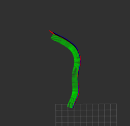
Localization node estimating the position of GroundsBot as it moves around.
The coverage planning node accepts a polygon drawn by the user interface and returns a set of GPS waypoints in a zig-zag pattern for the robot to follow to cover the entire input area. The node minimizes the number of turns required by GroundsBot to cover the area. It does this by slicing the polygon along the direction of the longest side. Once the polygon is sliced, a list of GPS waypoints are returned for visualization on the UI. When the points are approved, they are sent to the waypoint serving node to send waypoint goals to GroundsBot.
Zig-zag coverage path generated by the Boustrophedon node.
The waypoint-serving node reads in this set of GPS waypoints and publishes a target waypoint for the planning node to subscribe to. The node keeps track of all the waypoints GroundsBot has visited and increments through the list in order, publishing a single waypoint at any given time. This published waypoint is then used by the global planner to generate a target path.
The global planner brings together the pose estimate from the localization node, the target waypoint from the waypoint-serving node, and the costmap containing obstacle information from the perception subsystem. The costmap, however, is not in the necessary format. The costmap is modified to provide rewards (less cost) along the direct line from the last waypoint to the next waypoint. This creates a behavior that attracts GroundsBot to stay on a straight line and navigate along the edges of obstacles. The modified costmap is then used by ROS navstack to generate a global plan. Navstack uses Dijkstras algorithm to find an optimal path to the target waypoint. Once the path is generated, it is sent to the local planner.
The local planner takes in the global plan and GroundsBot’s current pose estimate, then outputs velocity commands to the Arduino node. The node first gets a carrot waypoint from the global plan. The carrot waypoint is a pose along the global plan about 2-3 meters in front of GroundsBot. This waypoint updates at a frequency of 15 Hz, so it is always a waypoint just ahead of GroundsBot’s current position. The node then uses the current pose published by the localization node and the carrot waypoint to determine a trajectory to move in. Specifically, the node uses two PID controllers to minimize GroundsBot’s yaw error towards the waypoint and minimize GroundsBot’s distance towards the waypoint. The two PID controllers output a forward and angular velocity for GroundsBot to move at.
In the end, the wheel velocities drive GroundsBot toward the carrot waypoint which pulls GroundsBot along the global path. This navigates GroundsBot to each waypoint, following the coverage plan for the original input area. The resulting path allows GroundsBot to cover a given area while avoiding obstacles at the same time.