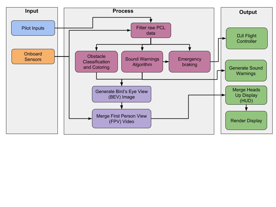
The complete system operation is depicted in a block diagram capturing functions and overall flow of information. Here, we have divided the system into 3 stages which are happening continuously and concurrently. These are:
- Input:
- Pilot Inputs: Our system being an assistive technology always has a pilot-in-the-loop. The pilot operates the quadcopter by relying only on the FlySense interface
- Onboard Sensors: They are primarily used for perception and state estimation.
- Process:
- The raw velodyne point cloud data is filtered to extract the relevant points based on the flight envelope and pilot inputs.
- The filtered point cloud data is sent into 3 different channels, one for obstacle danger classification and coloring, another for the sound warnings algorithm and final channel for the emergency braking for obstacle avoidance.
- The obstacle coloring and sound warnings merge together into the Bird’s Eye View (BEV) image.
- The FPV video is merged with the BEV and published.
- The emergency braking code produces control commands that are sent to the flight controller.
- Output:
- The sensor information is rendered as a Heads Up Display (HUD) and overlaid on top of the FPV and BEV video.
- Sound warning are generated based on the dangerous obstacle to alert the pilot.
- The flight controller executes control commands to force braking of the quadcopter depending on a potential collision.