The overall system comprises the Stretch RE1 mobile manipulator as the primary robot. For HRI capabilities, an external microphone is mounted on the base of the robot. Additionally, an iPad is mounted on the head of the robot for displaying the robot’s face. Our overall software architecture comprises several different subsystems operating in tandem, coordinated by 4 different layers of finite- state machines. Level 1: A high-level mission planner coordinates the global status of tasks that are executed. Level 2: Each subsystem has its own local FSM that is used to execute sub-tasks. Level 3: Our manipulation subsystem has several complex algorithms that require their own FSMs executing within Level 2 FSMs. Level 4: All of our subsystems are orchestrated by action servers which are based on a low-level FSM.
Our major subsystems are described below:
Mission Planner
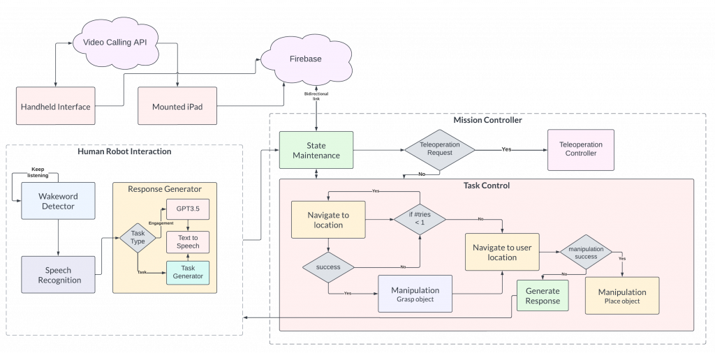
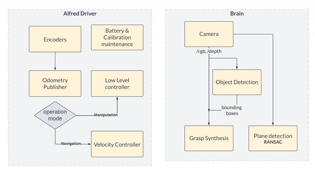
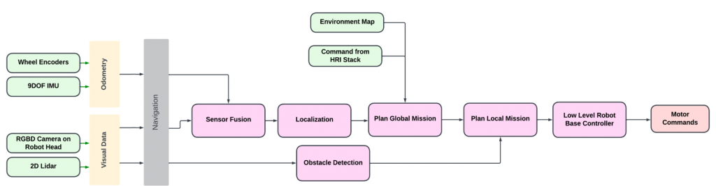
The Mission Planner subsystem enables the integration of the three primary subsystems of our robot: HRI, Navigation, and Manipulation. The Mission Planner manages the current state of the system through a finite state machine (FSM). This FSM triggers different sub-systems of the robot to be activated and perform their part in the larger task. Additionally, all the perception-related computation was performed on a remote GPU device, called the Brain. For low-level robot control, we have developed our own wrapper around the Stretch RE1’s low-level controller, called Alfred Driver. The various architectures governing the Mission Planner’s decision-making and the Brain / Alfred Driver’s work are shown in Figures 1 and 2.
We use a single script in order to launch our entire robot in a coordinated manner. When launched, our custom software automatically ensures robot calibration, runs system checks to ensure all sensors are operating nominally, and ensures that all ROS nodes are running nominally before the robot is ready to receive commands.
Human-Robot Interaction
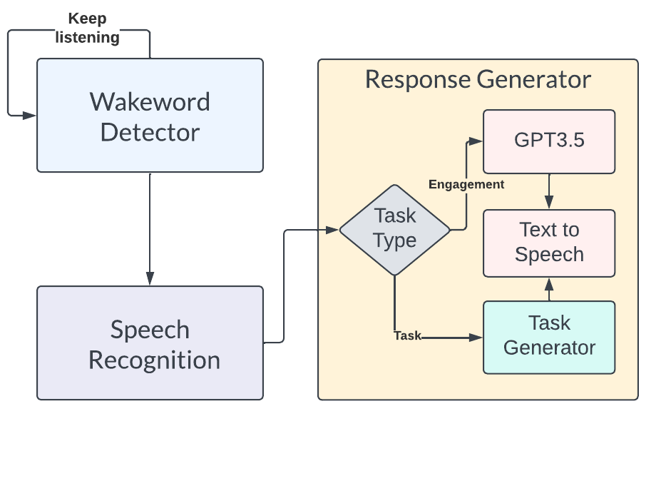
The above figure shows the HRI subsystem architecture in a flowchart. The Human-Robot Interaction subsystem (HRI) enables the Speech Engagement and Telepresence capabilities of the robot. The Speech Engagement subsystem was implemented with Picovoice for trigger word detection, Google Cloud’s speech-to-text API for speech parsing, and DeepMind’s Neural2 API for life-like voice synthesis. Additionally, ChatGPT was integrated into the HRI subsystem to handle social engagement requests. The trigger-word detector is always running in the background. When the user says the trigger word, the speech-parsing API is activated. The user’s subsequent speech is then parsed and the mission planner activates the respective subsystem to perform the desired task. If the user’s request is identified as a pick-and-place command, the mission planner performs task allocation to appropriately identify the desired object to be placed. If the user’s request is identified as a social-engagement command, the mission planner offloads the task to ChatGPT to generate a response. Finally, the robot gives feedback to the user through a speech command which appropriately addresses the user’s request.
[Add cropped video of HRI part with help from atharva]@apusalka
The HRI subsystem’s telepresence capabilities include teleoperation using a handheld interface UI and video-calling implemented with the Agora API. For enabling wireless communication for video calling and teleoperation, the Firebase cloud service is used. Additionally, an iPad is mounted on the robot’s head to display the robot’s face, as well as a video-calling screen. The HRI subsystem’s functioning can be observed in figures below.


Fig. 6: Teleoperation test
Navigation
The navigation subsystem is responsible for moving the robot in the operating environment from an initial location to the desired location of the object, and back to the initial location (where the object is to be placed). It is implemented in Python and C++ using the ROS Noetic platform. At a high level, the navigation subsystem performs functions such as Mapping, Localization, Motion Planning, Dynamic Obstacle Avoidance, Controls, and Actuation. The overall architecture of the navigation subsystem is shown below.
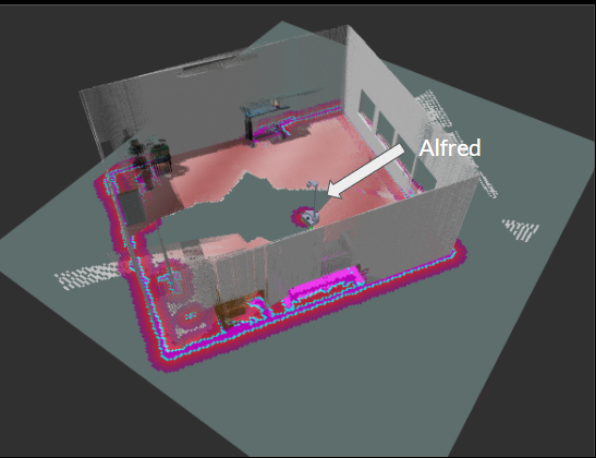
The development of the navigation subsystem started with the generation of a 2D map of the AI Maker Space (test environment). This was generated using SLAM with the help of the gmapping package in ROS. Given that the position of the Stretch RE1’s 2D Lidar is at knee-height, several static objects in the environment, such as tables, were not included in the initial map generated. In order to prevent the robot from planning paths through these regions, the 2D map was manually edited using a software called GIMP. Specifically, regions, where the robot should not traverse, were marked as unknown regions (grey color) in the map of Fig 8.

For localization, we used the Adaptive Monte Carlo Localization algorithm, implemented in the amcl package in ROS Noetic. This algorithm would use the robot’s real-time odometry and lidar data for the prediction and update steps, respectively. For robot path planning and controls, the movebase ROS library was used. We used Dijkstra’s algorithm (Navfn ROS) for global path planning and the Dynamic Window Approach (DWA) algorithm for local path planning and controls. While these planners usually generated feasible paths through the test environment, there were times when the robot would struggle to navigate around an obstacle. In these situations, the robot would trigger its recovery behaviors. The recovery behaviors used by our navigation subsystem were Clear Costmap Recovery, Rotate Recovery, and Moveback Recovery. The Moveback Recovery behavior is a custom plugin developed by the team that commands the robot to move back by a set distance and replan a path, in cases where the other two recovery behaviors fail. Additionally, we extensively tuned ROS parameters in Costmap, Planner, and AMCL packages to optimize the robot’s performance in the test environment. An image depicting the robot avoiding obstacles during navigation is shown in Figure 8.
3D Navigation: Besides 2D map-based navigation, we also implemented Real-Time Appearance-Based Mapping (RTAB Map). It is a graph-based SLAM approach based on an incremental appearance-based loop closure detector. Fig. 9 shows a 3D map created after running this SLAM approach in a simulation environment. This approach is less susceptible to navigation across thin objects in comparison to 2d navigation since it uses additional modality (RGBD camera) to create a map instead of just a 2D LiDAR. We didn’t deploy this approach for spring validation demonstration due to time constraints and test time problems.
Manipulation
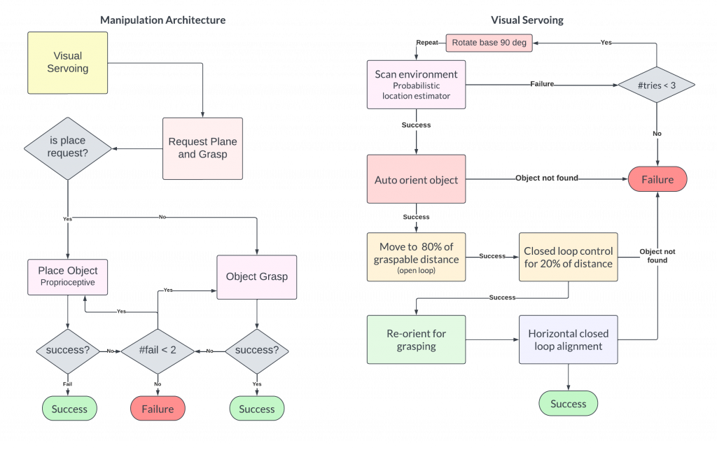
The goal of the manipulation subsystem is to successfully pick the desired object and place at the desired destination once the navigation is completed. Our manipulation subsystem handles both pick as well as place requests. Once a pick request is issued to the subsystem, we execute tasks in sequence as described in our architecture in Figure 10.
The detailed working of manipulation subsystem can be defined in the following steps.
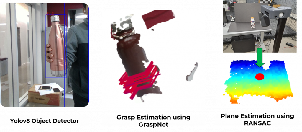
- Visual Servoing: The visual servoing algorithm is responsible for finding the object of interest in the environment and automatically aligning the robot to a graspable position. Each part of the algorithm involves three steps: a) Scanning: Using the head camera assembly (Intel RealSense D435i) on the robot, we pan the camera across the environment while parallelly detecting all objects in the environment using the Yolov8 object detector. Using this, we estimate a ground truth location of each object in the world frame and employ a Maximum Likelihood Estimator (MLE) based on a weighted probability score that decays in a hyperbolic fashion with respect to the distance of the object from the camera. This helps filter out all objects that are improbable (such as bottles on the ceiling/floor, etc.). The perception capabilities can be seen in Figure 12. b)Visual Alignment: Once we estimate the location of the object, we perform a sequence of closedloop control steps that uses visual feedback in order to align the robot within a maximum graspable distance threshold. This allows the object to be within the workspace of the robot manipulation. c) Recovery: We employ several recovery schemes in order to ensure that the robot doesn’t reach an irrecoverable state. These schemes are described in Figure 10.
[Add visual servoing video here] @pvenkat2
- Grasp Generation: We developed three methods for grasp generation, namely GraspNet, GGCNN, and Median Grasp. We primarily use the GraspNet algorithm in order to pick a location on the object to grasp. GraspNet is a model trained on a large-scale database of objects and grasps. We obtain a 6D grasp from point clouds observed from the camera focused on the object of interest. However, since we have constraints on the graspable region due to the design of the end-effector, we developed our own heuristics that allow us to generate grasps feasible by our robot. We use the Median Grasp strategy as a fallback in case GraspNet does not produce high-quality grasps. Median Grasp takes in the point cloud of the object and returns the median point in the object as the grasp location. Figure 12 shows these results.
- Plane Detection: We employ a plane detection algorithm based on the RANSAC scheme in order to estimate the plane from which an object is picked. We use this in order to estimate the height at which the object is grasped from the table. This is useful as it gives us an estimate of the clearance
required for placing the object on a surface. - Motion Planning and Control: Our current system employs a basic control pipeline that does not consider obstacles within the workspace of the manipulator. We execute Cartesian motions that reduce the probability of collisions.
- Grasp Success Validation: To verify if the grasp is successful, we additionally trained a logistic regression model which classifies ‘success’ or ‘fail’ based on the gripping effort. We collected a small dataset of diverse objects and gripping configurations and trained a model based on it.