Functional Architecture
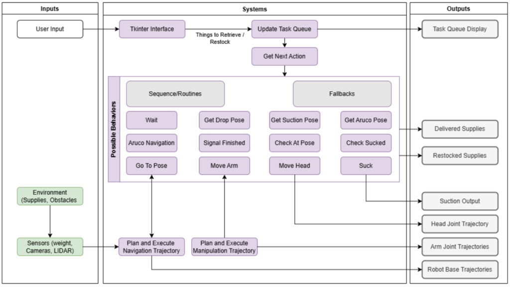
The functional architecture diagram illustrates the core components and processes of the system, showing how information flows from initial inputs to final outputs. It is divided into three main sections: Inputs, Systems, and Outputs, arranged from left to right to reflect the logical sequence of operations. Processes depicted vertically in parallel indicate simultaneous activities.
Inputs:
- User Input: Represents commands or tasks provided by the user via a graphical interface (Tkinter).
- Environment: Includes sensory data collected from the hospital environment, such as obstacle information and supply status, through sensors like cameras, LiDAR, and weight detectors.
Systems: The central section outlines the core processing components:
- Task Management: The Tkinter Interface captures user commands and updates the Task Queue. The system processes these tasks via the Get Next Action module to determine the next steps.
- Behavior Module: Comprises sequences and routines (e.g., wait, check at goal, suction, and move arm) as well as fallbacks for handling exceptions or errors (e.g., move head, retry suction).
- Trajectory Planning and Execution: Handles autonomous navigation to the target location and executes manipulation tasks to retrieve or restock supplies.
Outputs:
- Task Queue Display: Shows the real-time status of tasks in progress or completed.
- Delivered Supplies: The physical delivery of items to operating rooms or users.
- Restocked Supplies: The placement of items in designated locations.
- Arm Joint and Robot Base Trajectories: Low-level outputs that control the robot’s movements.
This functional architecture integrates the retrieval and manipulation pipelines to ensure efficient navigation, item handling, and coordination in hospital environments, ultimately enhancing the workflow of medical logistics.
Cyber-Physical Architecture
Cyber-Physical Architecture for Spring Validation Demo

Cyber-Physical Architecture for Fall Validation Demo
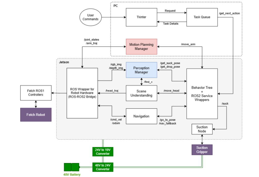
The cyberphysical architecture in for the ORB system demonstrates a strategic division of computational resources between two main processing units: a Jetson device and a PC. The Jetson handles the majority of the computational workload, including the perception modules, navigation systems, Behavior Tree execution, and the critical ROS2-ROS1 bridge functionality. This separation allows for efficient processing of sensor data and real-time control operations.
The PC component focuses on two specific but crucial elements: the user interface and motion planning pipeline. This architectural decision was driven by the motion planning system’s high memory requirements for voxel creation and package compatibility issues on the Jetson platform. The PC hosts a Tkinter-based GUI where user commands are processed and managed by a Task Queue system that implements a get_next_action protocol for sequential task execution.
The motion control system, centered on the Motion Planning Manager within the PC, processes joint states and arm trajectory data while coordinating with the ROS wrapper to execute precise movement commands. Meanwhile, on the Jetson, a comprehensive perception system includes the Perception Manager for processing RGB and depth imagery, a Scene Understanding module for environmental interpretation, and a Navigation subsystem utilizing odometry and pose data.
The system’s hardware interface layer, implemented on the Jetson, features a dual-ROS bridge architecture. The ROS Wrapper serves as a bridge between ROS1 and ROS2, while the Behavior Tree with ROS2 Service Wrapper manages high-level robot behaviors. This integration enables seamless communication between the Fetch ROS1 Controllers and the robot’s physical components.
Power management is handled through a cascaded conversion system, beginning with a 48V battery as the primary power source. This power is then stepped down through a 48V to 24V converter, followed by a 24V to 19V conversion stage to meet various component requirements. The end effector system features a Suction Gripper controlled through a dedicated Suction Node, which receives commands from the Behavior Tree for precise object manipulation tasks.