Fall 2026 Updates
Onboard Perception (Cosmos-Reason2-8B):
To eliminate the Wi-Fi dependency and enable continuous perception, the perception pipeline now runs fully onboard: a text query is grounded by the VLM, the grounded region is segmented, and the target is tracked in 3D using TensorRT on the Orin.
| Test | Measurement |
|---|---|
| Target grounding (TPR) | 100% SR (51/51) |
| Absent-target rejection (TNR) | 79.6% SR (39/49) |
| Grounding latency | ~1.67 s (down from a 7.18 s baseline) |
| Tracking throughput | ~12 FPS |
Several deployment paths were benchmarked for the onboard VLM; TensorRT Edge-LLM with FP8 gave the best accuracy/latency trade-off:
| Deployment path | Parsed responses | Mean latency |
|---|---|---|
| vLLM BF16 + FP8 KV cache | 16/19 | 3.22 s |
| Edge-LLM FP16 | 17/19 | 3.42 s |
| Edge-LLM FP8 | 19/19 | 2.08 s |
| Edge-LLM NVFP4 + FP8 vision | 12/19 | 1.16 s |
| Edge-LLM NVFP4 + FP16 vision | 11/19 | 1.17 s |

Camera Mount and Hand-Eye Calibration:
The camera mount was redesigned and a camera–LiDAR calibration was performed to estimate the camera extrinsics. A residual remained because the LiDAR pose in Unitree’s URDF is incorrect, so relative calibration alone could not fix the camera pose in the robot frame. The team therefore added a hand-eye calibration: ICP aligns the RGB-D point cloud of the robot hand with the hand mesh placed by forward kinematics, which corrects the camera; the relative camera–LiDAR transform is then used to correct the LiDAR.


Target Pose Filtering for Button Pressing:
An EKF on the body pose was added, segmentation noise is rejected to stabilize the object pose, and a Kalman filter runs on the target pose. The target pose is now much more stable during the approach.

Spring 2026
Vision-based Elevator Floor Detection:
The pipeline detects and reads the elevator floor indicator from camera images in a frame-by-frame manner. First, the input image is spatially cropped to reduce background noise, typically keeping the top half and central region where the panel is likely to appear. A vision-language model (VLM) is then used to localize the floor indicator based on a semantic query, producing a bounding box for the display.
To improve stability, detections across consecutive frames are temporally smoothed using simple overlap-based matching and averaging. The resulting bounding box is then expanded slightly and passed to a dedicated readout stage.
In the readout stage, the cropped region is processed using an HSV-based mask to extract illuminated pixels from the display. A percentile-based binarization is applied to enhance contrast, followed by a tighter crop around the foreground. The processed image is then fed into an OCR model with a restricted character set to obtain the final floor symbol. The output is formatted as structured data together with the detection result for downstream use.
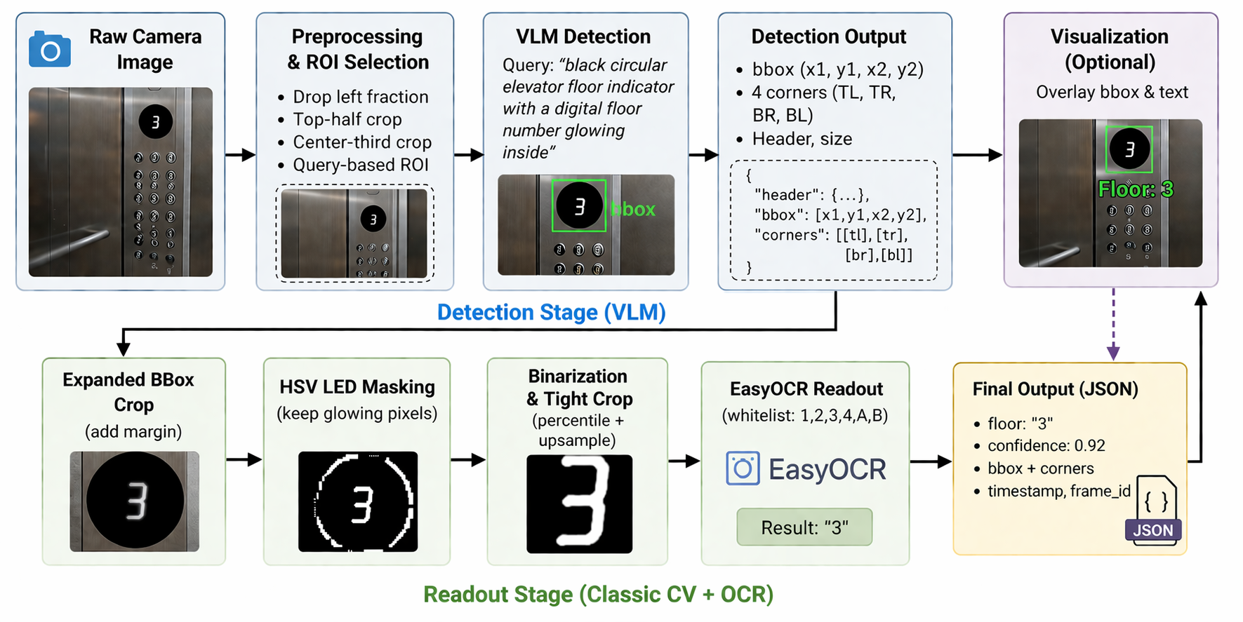
Fig: The Pipeline of Elevator Floor Detection.
IMU-based Elevator Floor Detection:
The imu based elevator floor detection uses the z-direction acceleration from imu to detect spikes, and then split the floor transition based on the time interval between a pair of spikes.
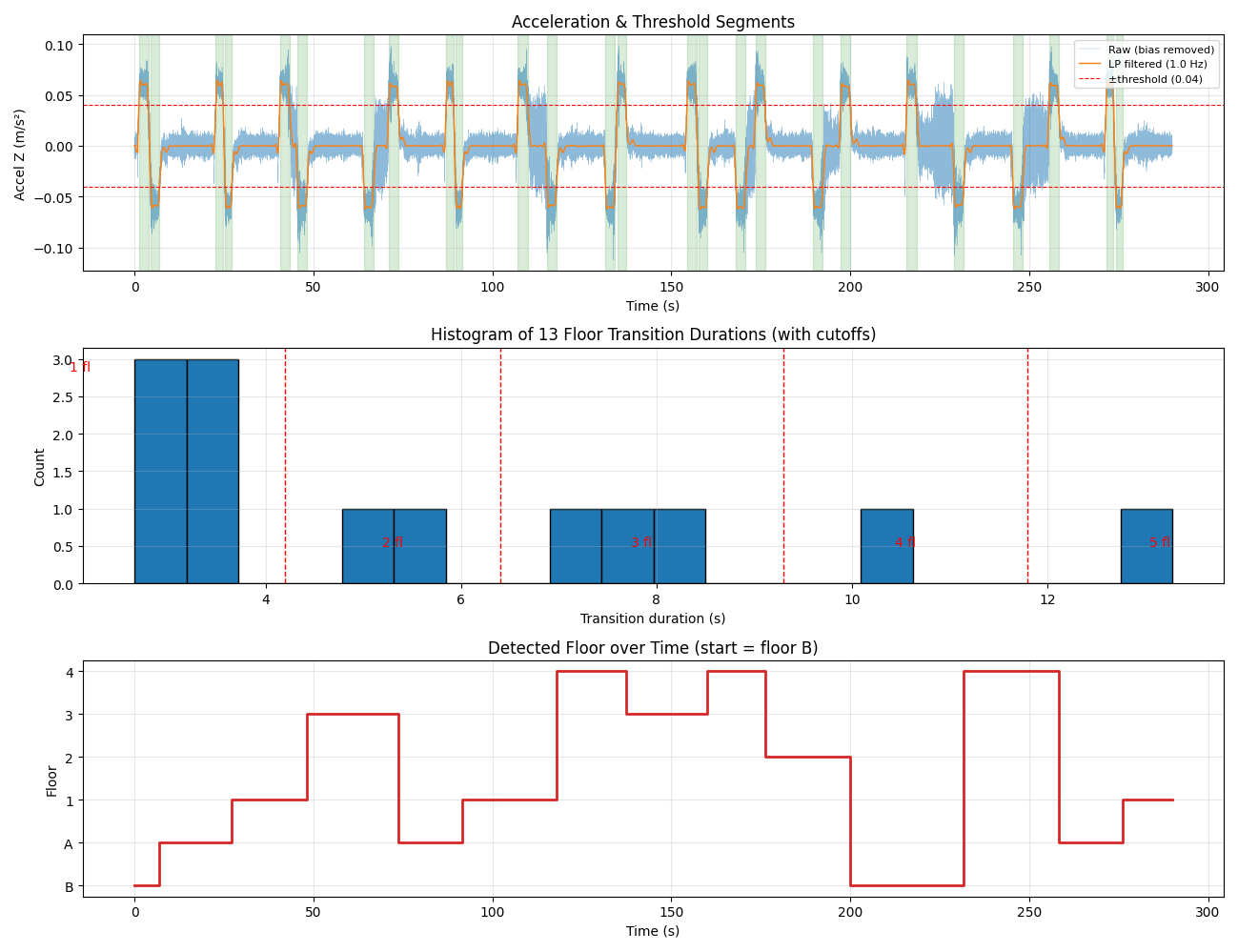
Fig: A demonstration of spike detection and time duration distribution.
Button Detection:
The button pose detection pipeline uses a VLM-based vision module to detect elevator button panels from the live camera stream and produce a 6-DoF
target pose (position and orientation). The detected pose is transformed through the robot’s frame chain (camera → base → arm) so the arm controller can servo toward the button. Stability guards reject single-frame false positives and hold the last valid pose briefly to prevent oscillation, making the
detection repeatable enough for downstream arm control to execute button presses reliably.
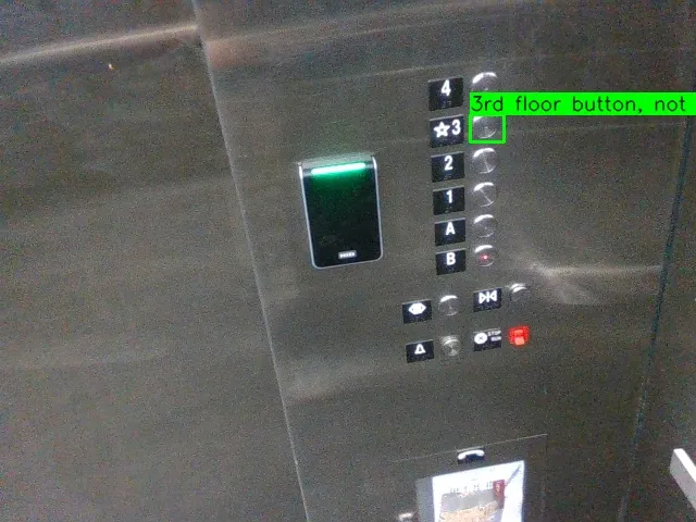
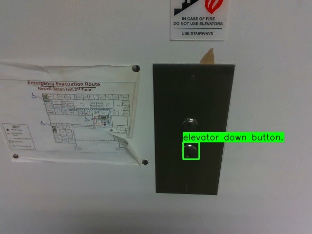
Fig: Button Detection Results in Elevator with Language Prompt (for both in and out elevator).
Door State Detection:
A ROS 2 action server was developed to detect elevator door states by monitoring real-time point cloud density changes within a tracked region. The system leverages a vision-language model to localize and track the elevator door, then calibrates baseline point count and depth over an initial observation window. During operation, incoming point clouds are depth-filtered around the calibrated region to remove noise, and a smoothed percentage metric—based on deviations from the baseline—is used to infer door state. A configurable threshold determines whether the door is open or closed, while robustness is ensured through startup grace periods, data timeout handling, thread-safe processing, and enforcement of single active monitoring sessions.
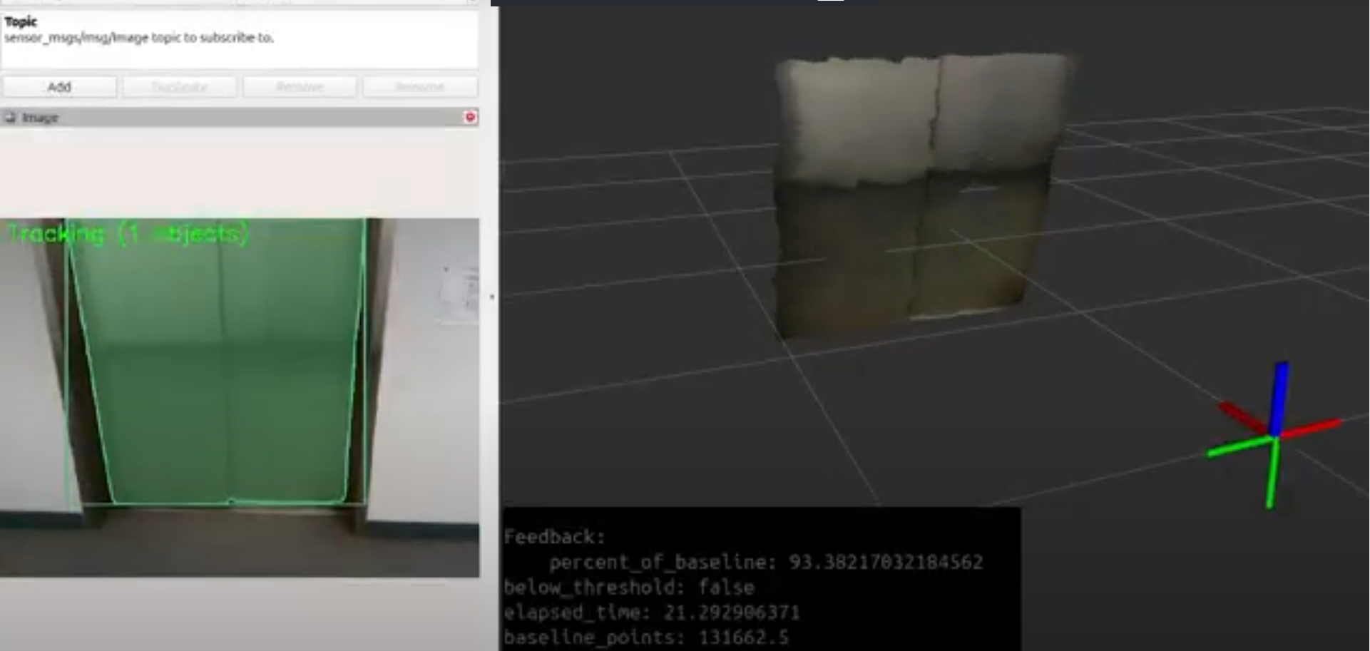
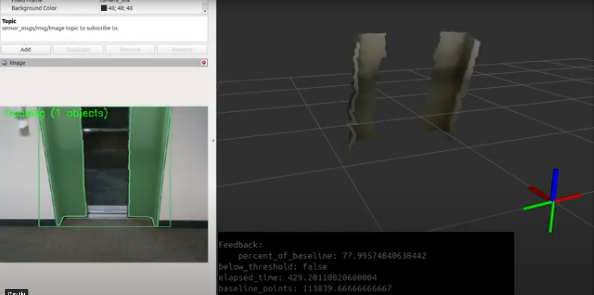
Fig: A Visualization of Door State Detection.