Our PCB is a 24 V power distribution and supervisory control board that manages power delivery from an upstream supply to a downstream system while providing safety control and monitoring.
The board takes a nominal 24 V DC input and splits it into two main paths. One path is stepped down using an MP1584 buck regulator to generate a low-voltage rail for onboard electronics, including an ESP32-S3 module that serves as the main controller. The other path keeps the 24 V supply and routes it through a relay-based switching stage, allowing the system to connect or disconnect the downstream load.
The relay is controlled by a low-side MOSFET driver using an AO3400 N-channel MOSFET. A gate resistor is included to ensure stable switching, and a flyback diode across the relay coil protects against voltage spikes during turn-off. The board also includes an emergency-stop (E-stop) input. This signal is filtered through an RC debounce circuit before being read by the controller to ensure reliable operation.
During operation, the ESP32-S3 monitors the E-stop signal and applies control logic to drive the relay. When enabled, the relay closes and allows 24 V power to pass to the output connector; when disabled, the power path is cut off. Overall, the PCB integrates power regulation, control logic, safety input conditioning, and protected switching into a single compact system.
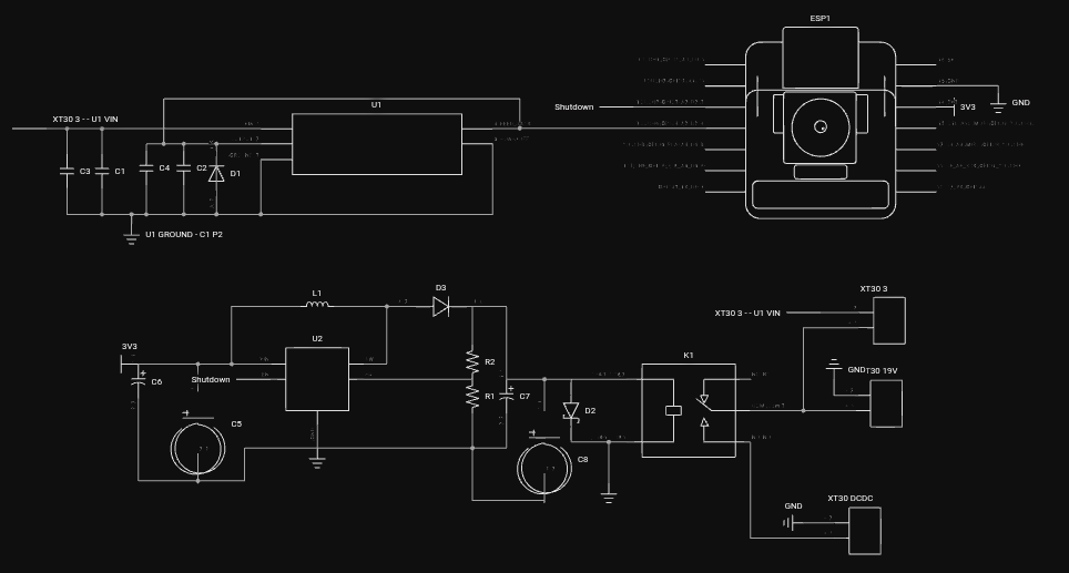
Fig : PCB Schematic.
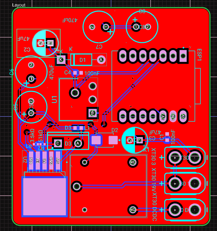
Fig : PCB Layout Design.
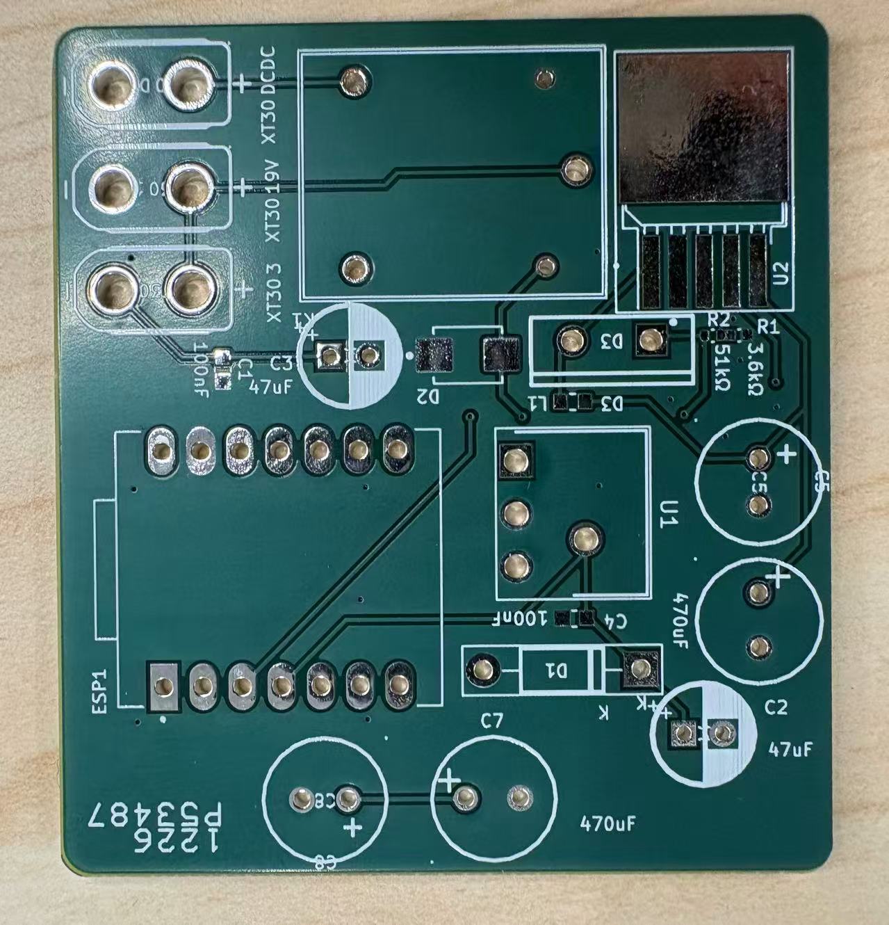
Fig : Printed PCB Board.
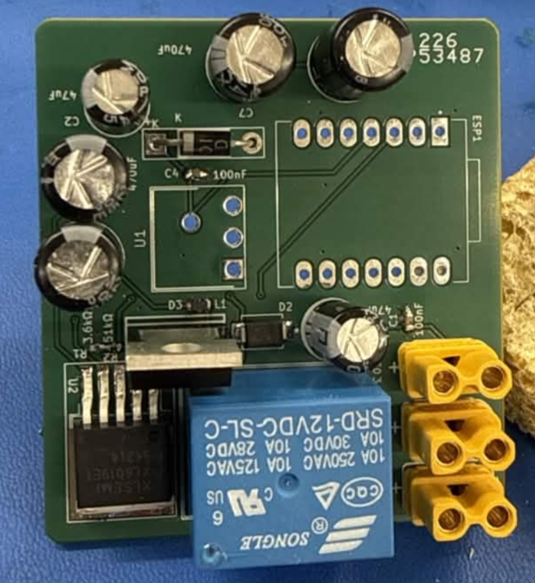
Fig. PCB Board with Mounted Components.