System Requirements
Mandatory Functional Requirements
- MF1: Locate Oil/Gas wellhead infrastructure with known heading in 25m2 area
- MF2: Autonomously maneuver to wellhead within one hour
- MF3: Positively ID as correct wellhead with 90% confidence
- MF4: Maintain hover position over dock within +/- 1m of dock position continuously
- MF5: Rigidly dock in five degrees of freedom
- MF6: Provide status feedback to user of current state at 0.1Hz
Desired Functional Requirements:
- DF1: Locate Oil/Gas wellhead infrastructure in low visibility with unknown heading in 25m2 area
- DF2: Positively ID as correct wellhead from visual object recognition with 90% confidence
- DF3: Align with dock located at known radius but unknown angle from wellhead within +/- 1m
- DF4: Detect obstacles
Mandatory Non-Functional Requirements:
- MNF1: Provides emergency stop for system with less than one second lag
- MNF2: Operable by a single person
Desired Non-Functional Requirements:
- DNF1: Reduce operator cost by at least one-half
- DNF2: Simulate low-visibility: Unable to get visual feed beyond 3m from camera/quadrotor
Functional Architecture
The figure below shows the reduced functional architecture for the team’s project. The functional architecture is broken down into three major sub-functions: “Locate and Identify Desired Wellhead”, “Move to Pre-Docking Position”, and “Dock on Wellhead”.
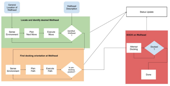
Simplified Functional Architecture
The next figure shows an expanded version of the “Locate and Identify Desired Wellhead” sub-function.
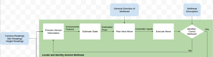
Locate and Identify Desired Wellhead Sub-function
The above figure clearly shows the flow of information into and throughout the sub-function. The main inputs to the system are: “Camera Readings, IMU Readings, and Height Readings”, “General Direction of Wellhead”, and “Wellhead Description”. Internally information is passed between each block in the fashion of: sense, plan, and act. This block is executed on a loop until the robot has identified the correct wellhead. Once it has identified the wellhead, the system changes to the “Move to Pre-Docking Position” state as shown in the figure below.
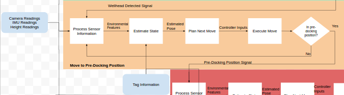
Move to Pre-Docking Position Sub-function
In figure above, the flow of information for the “Move to Pre-Docking Position” sub-function can be clearly seen. The inputs to this sub-function are: “Camera Readings, IMU Readings, and Height Readings” and “Tag Information”. This tag information is for the dock. The internal flow of information is the same loop as the “Locate and Identify Desired Wellhead” sub-function, except for the stopping criteria. The stopping criteria is “in pre-docking position” which is determined by mandatory functional requirement 4: Maintain hover position over dock within +/- 1m of dock position continuously. Once the robot has reached the stopping criteria it moves into the “Dock on Wellhead” state as shown in the figure below.
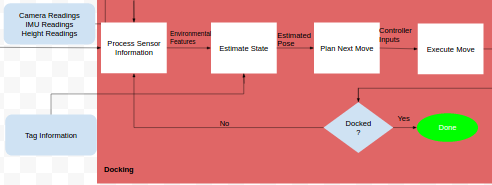
Docking Sub-function
The figure, above, shows the final sub-function and state of the system, docking. Once the robot has reached the pre-docking position it will make its docking descent and complete its task of docking. The main inputs to the system are: “Camera Readings, IMU Readings, and Height Readings” and “Tag Information”. In our final implementation, the APRIL tag was used to simulate the wellhead detection.
Cyberphysical Architecture
The cyber-physical architecture, shown in Figure 10, has been broken down into five main parts: Infrastructures, sensors, single board computer, motor control & UAV, and user interface. We have organized our cyber-physical architecture based on how the systems are physically organized and interact.
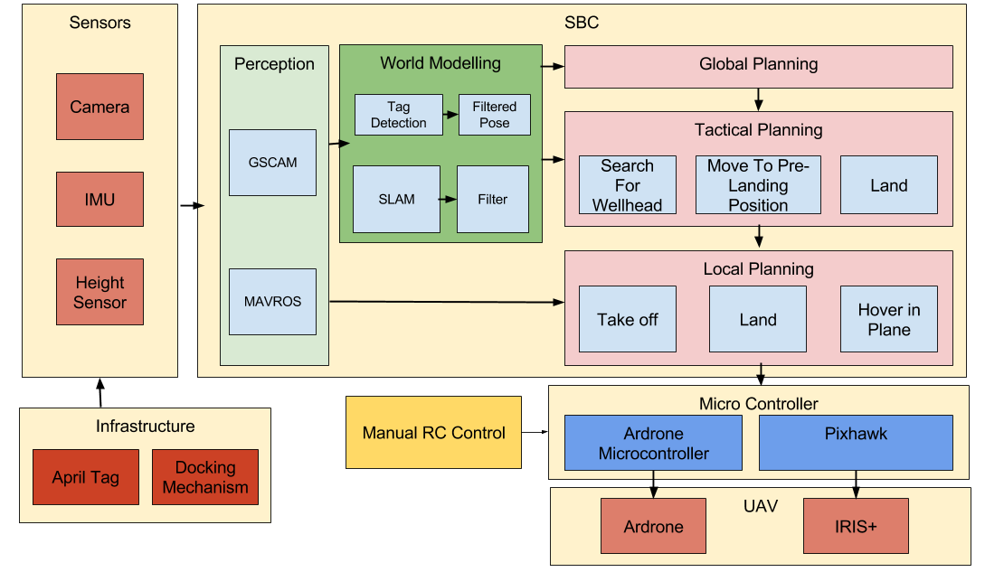
Cyber-physical Architecture
The infrastructure comprises of the APRIL tag and the docking mechanism. The APRIL tag consists of features that can be easily detected using image processing. These features are then used to estimate the pose of the robot with respect to the tag. Docking mechanism is designed to constrain the robot in 5 DOF.
The sensors consists of the camera, IMU, and height and optical-flow sensor. The downward facing camera allows the drone to view the dock and ground april tags. The IMU is used for the drones state-estimation. A sonar height and an optical flow sensor is also used for the state estimation, localization and height stabilization.
For the single board computer we have an underlying software architecture that implement the ‘Toaster-Wedding Cake’ model. The ‘Toaster-Wedding Cake’ model constitutes the flow of data and information in a sense-plan-act format. The toaster is the vertical blocks of perception and world mapping. The systems perceives the environment through the sensors, then develops a model of that environment. The wedding cake is the flow of data through the high level global plan to the low level local planning. This planning structure dictates the actuation the system will have on the environment.
The microcontroller is the hardware running the low level controller and is a part of the UAV. The microcontroller and UAV sections are broken into two parts. The AR.Drone2 is the drone we used for testing of high level searching algorithms and exists as a backup if Iris+ cannot perform the necessary tasks. The high level software will be run on the single-board computer with information being passed to it from the wireless communication and low level microcontroller.
System Design Descriptions
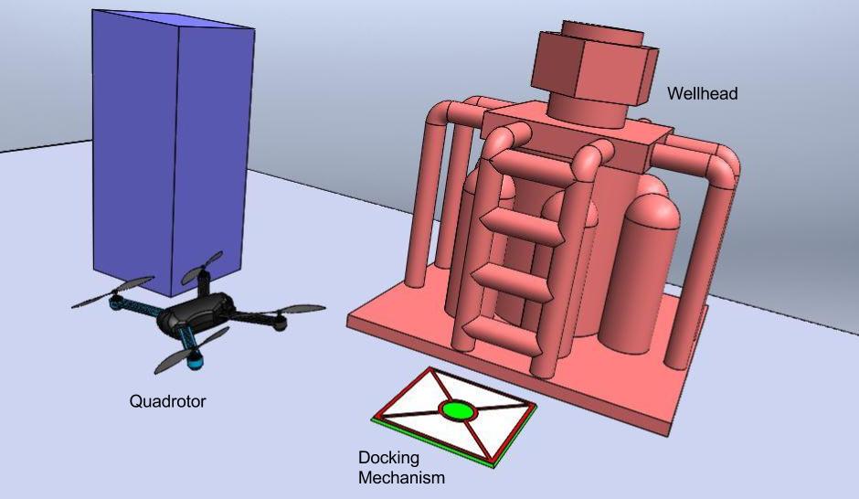
The full version of our system is shown below live showcasing the quadrotor and the dock.
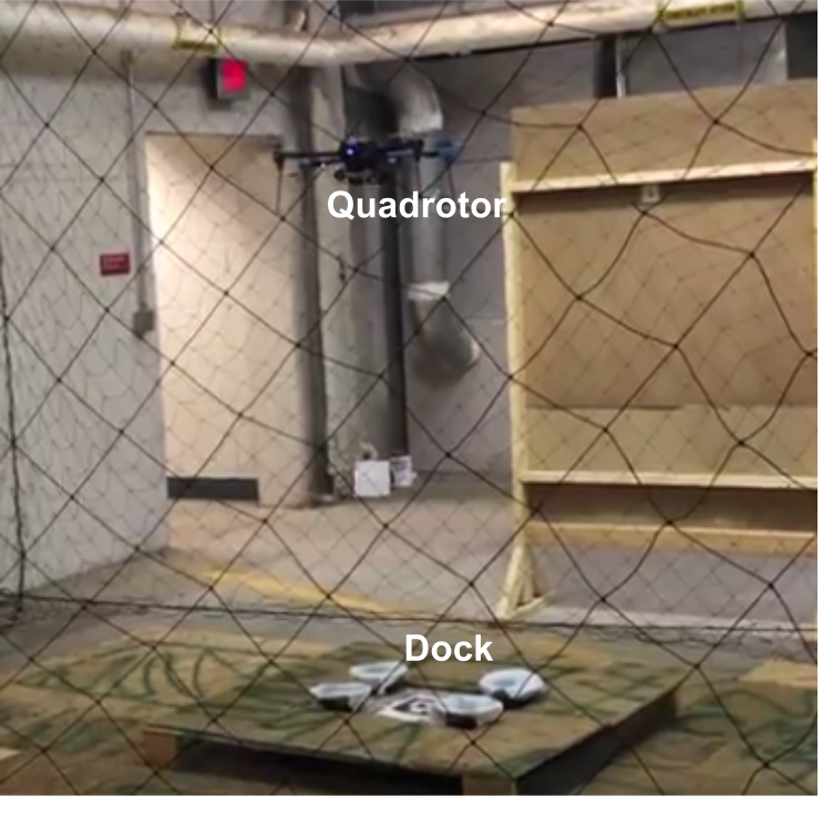
The figure above is a graphical depiction of our project. The quadrotor searches for the wellhead and identifies it by processing the images from the on-board camera. Then the quadrotor moves to the pre-docking position and docks to the docking mechanism.
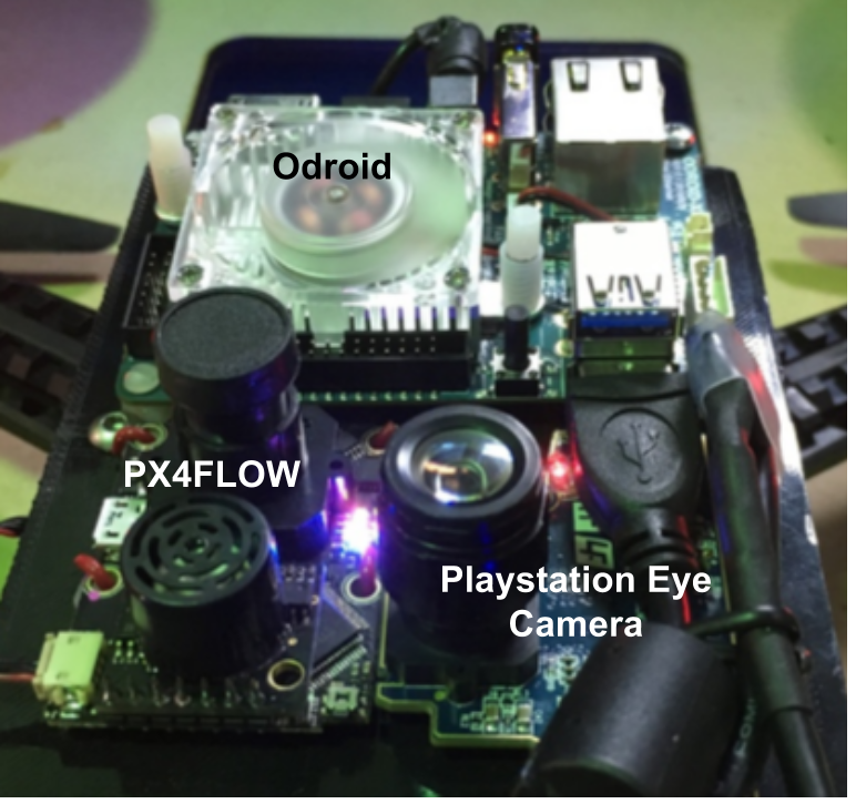
The figure below shows the hardware system on the quadrotor.
Infrastructure Subsystem
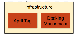
Infrastructure
Landing a quadrotor at desired a location is a hard problem because of the turbulence in the airflow of the thrusters when the quadrotor is close to the ground. Hence, one of main design criterion was to be able to tolerate large variance in pose at which the quadrotor can approach the dock. To meet this requirement for the docking mechanism, we are using four cones to funnel the quadrotor down to the desired location, as shown in the figure above. Using this strategy we can tolerate larger tracking errors in our control algorithm during landing. We will be manufacturing a mock-up of the wellhead infrastructure in the next semester. The details of the tag are covered in the perception subsystem.
Sensor Subsystem
The table below shows the description of the components of the sensor subsystem, and the figure below it shows the components of the sensor subsystem mounted on the Iris+.
Sensor Subsystem Description
| Sensor | Sony Playstation Eye | PIXHAWK | PX4FLOW KIT | |
| Function | Downward camera whose feed is used to detect the APRIL Tags | Flight controller to run the attitude control loop of the quadrotor | Sensor to provide visual odometry estimates | |
| Features | Supports a framerate of 120hz at 320×240 resolution. | ST Micro L3GD20 3-axis 16-bit gyroscope
ST Micro LSM303D 3-axis 14-bit accelerometer / magnetometer Invensense MPU 6000 3-axis accelerometer/gyroscope MEAS MS5611 barometer |
PX4FLOW V1.3.1 optical flow sensor smart camera compatible with PX4 PIXHAWK flight controller. Used to obtain visual odometry updates | |
| Image | 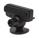
source: http://amazon.com |
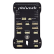
source: https://pixhawk.org |
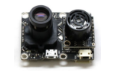
source: https://pixhawk.org |
|
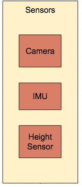
Sensors
World Modeling Subsystem
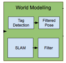
World Modeling
As shown in the figure above, the world modelling subsystem consists of the following three nodes:
- Pose Estimation: This node will estimate the pose of the quadrotor in the world frame.
- Wellhead Detection: This node will estimate the position of the wellhead in the quadrotor frame.
- Obstacle Avoidance: This node will update the occupancy grid with the obstacles, once they are detected.
We did not focus on implementing these systems during the fall semester, however, we have experimented with some algorithms that will help us implement this system. The following are the algorithms that we explored:
APRIL tag detection
We used a library (http://people.csail.mit.edu/kaess/apriltags/) by Mike Kaess, written in C++ that detects APRIL tags and estimates the pose of the robot. We can use this to detect the wellhead and the docking mechanism.
The pose estimates from the april tag are given as the april tag frame with respect to the camera frame. This causes the frame’s coordinates to change as the camera frame rolls and pitches with the movement of the quadrotor. In order to remedy this, we inverted the frame in order to get the quadrotor in the april tag frame. This allowed us to get a frame that is fixed to the april tag and does not shift with rotation. This data in practice was found to be noisy. In order to provide better data, we implemented RANSAC in order to filter out the noisy data.
Lucas-Kanade based optical flow
We can use this algorithm to estimate the velocity of the quadrotor using the camera feed. Scale estimation is one of the major problems with this algorithms. We are using the PX4Flow sensor that implements this algorithm and estimates the scale using an integrated ultrasonic sensor which measures the distance to the ground. After consulting last year’s MRSD teams, we are confident that this solution works.
Mapping Subsystem
RTAB-Map (http://introlab.github.io/rtabmap/) is graph and node based system that uses SIFT features in order to find points of detection. It uses structured light in order to improve the performance of the stereo information. It prunes the graph based on a powerful TORO graph optimization technique in order to reduce computation. The algorithm uses a bag-of-words technique in order to detect loop closures.
Planning Subsystem
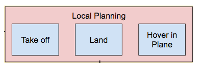
Local Planning
As shown in the figure above, we are using a 3 layered architecture for the planning. Each layer acts like a state machine for the layer below it. For example, the global planning starts with “Search For Wellhead”, on finding the wellhead, it transitions to the “Move To Pre-Docking Position”. On reaching pre-docking position, it transitions to the “Attempt Docking” state. Similarly, “Search For Wellhead” is a state machine that uses “Take off” and “Hover in Plane” states. For this semester we have implemented the entire local planning and hence, most of tactical planning on the AR.Drone. We demonstrated this functionality in FVE by doing a lawn mower search using the AR.Drone. The details of this are covered in the next section.
Local planner consists of the proportional-derivative position controller which was implemented in C++. We implemented the global and tactical planning nodes in python. This enabled us to the test the higher level code without recompiling. Hence, it decreased the time we took to develop and test the software once the local planner was implemented and tested. We leveraged the ROS Parameter server to serve as a “blackboard” of shared state variables such as controller gains, setpoints, and event flags which enable us to easily script behaviors for the entire system from nodes written in Python instead of relying entirely on hard-coded C++ behaviors. Using these setpoint parameters, we were able to script various movement patterns and conditional behaviors, including manual control of the sequence start time from the hand-held controller as well as automatic landing after completing a search sequence.
Hardware Subsystem
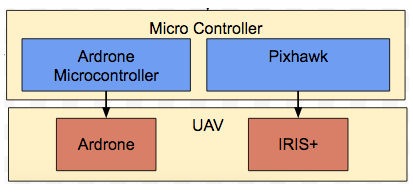
Microcontroller and UAV Subsystem
The figure above shows the components of hardware subsystem. The AR.Drone is reliable quadrotor system that we obtain from the MRSD storage at no cost to us. The AR.Drone acted as our initial test bed to run our high level search algorithms and code. The AR.Drone is also our fall back and risk mitigations if the Iris+ drone cannot perform our desired tasks. The drone does not require any extra hardware and is controlled via wifi from a host computer. It has a forward facing and downward facing cameras, and the downward facing camera doubles as an optical flow sensor.
The Iris+ drone is a commercially bought quadrotor that we are modifying to with sensors and a SBC. The Iris+ drone’s motors’ low level controls are commanded via Pixhawk, which also has a compilation of various sensors, such as 9 axis IMU, and barometers. It also handles our communication to the RC controller. The SBC will be communicating to the Pixhawk via UART to control the drone’s movements.