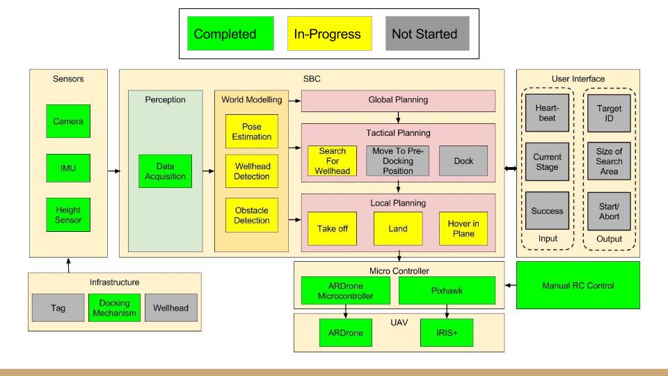
Full System Progress
The figure below shows the current system status as of the end of the Fall Semester:
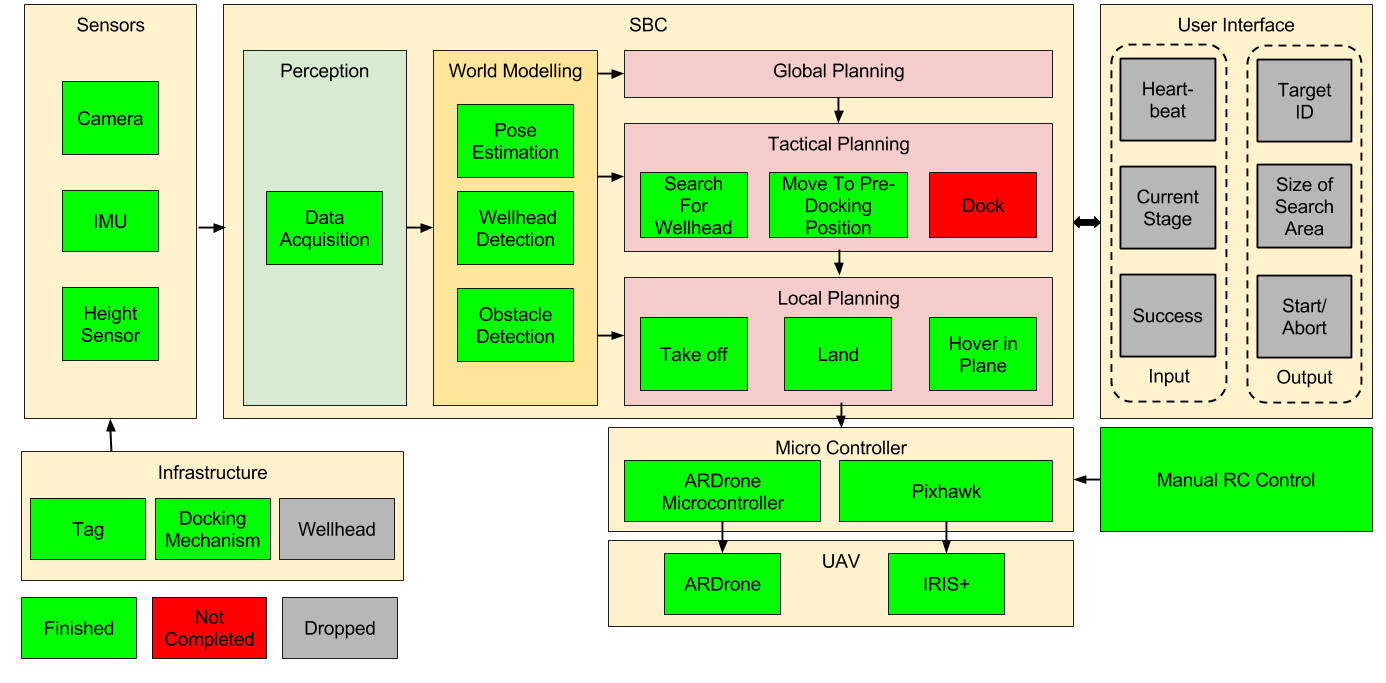
The figure below shows the final status of the project:
Infrastructure
The progress of the infrastructure subsystem is shown below:
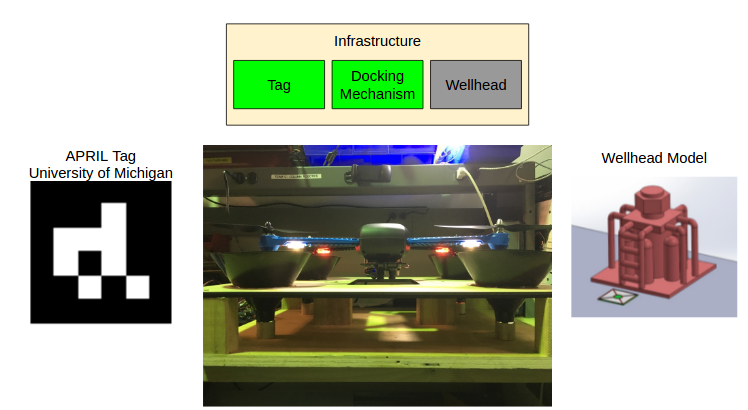
During the Fall semester, the dock had been fully designed and manufactured, the tag system has been researched, but the wellhead manufacturing has been moved to the Spring semester.
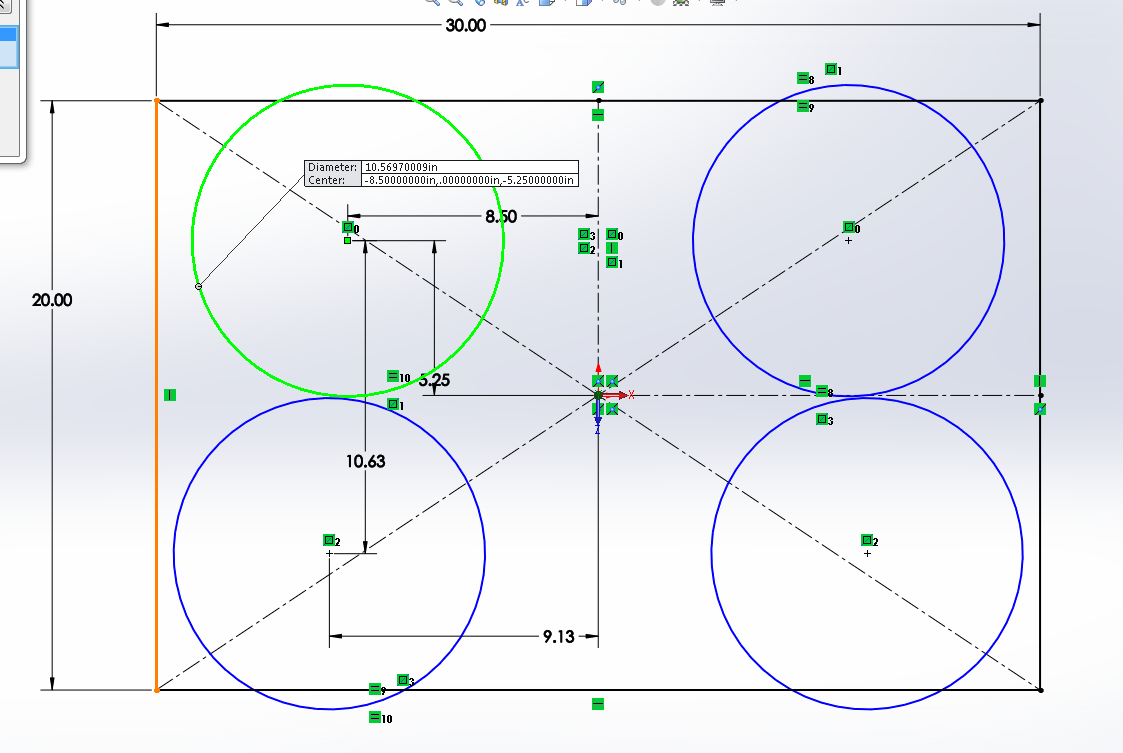
During the Fall semester, we designed our dock based on a cone system which was based on the original design shown below.
By the end of the Spring semester, the dock was painted in order to contain enough features for optical flow, and the April Tag system was fully implemented. We also decided that the wellhead infrastructure would not add anything to features of the system. We decided to drop it from the scope.
Sensors
The progress of the sensor subsystem is shown below:
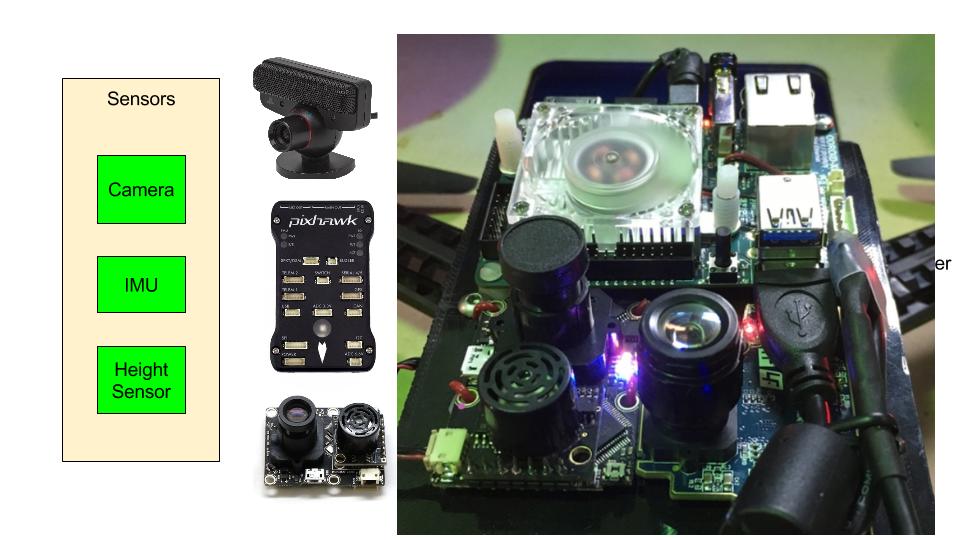
During the Fall semester, the sensor hardware and software communication have been completed on the Iris+. During the Spring semester, a second set of sensors will be mounted to a second Iris+ that will be used for backup.
World Modeling
The current status of the world modeling subsystem is shown below:
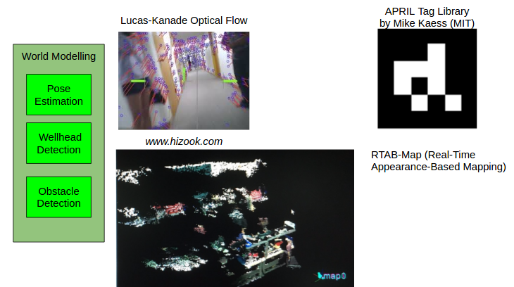
During the Fall semester, world modeling was implemented on the AR.Drone2.0. In the Spring semester, we will be working on implementing world modeling on the Iris+.
During the Spring semester, we implemented code to be able to estimate the pose of the robot from April Tags.
We calculated the inverse of the transformation matrix so that we could find the quadrotor with respect to the april tag’s frame. The source code for this can be found: https://github.com/ColumnRobotics/column/blob/master/src/rectified_april_tag.cpp.
We found that these measurements were quite noisy, so we filtered the estimates using RANSAC. Our source code for this can be found: https://github.com/ColumnRobotics/column/blob/master/src/BodyPoseFilter.cpp.
The main function of the world modelling source code can be found here: https://github.com/ColumnRobotics/column/blob/master/src/world_modeling.cpp.
Planning
The progress of the planning subsystem is shown below:
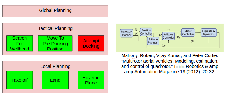
During the Fall semester, the planning subsystem was implemented on the AR.Drone2.0.
During the Spring Semester we worked a considerable amount on getting a base framework for planning.
The global planner was handled by a bash script that called all of the nodes, launch files, and other global frameworks. It also determined the overall behavior. This bash script is found here: https://github.com/ColumnRobotics/column/blob/master/launch/global_planner.bash.
The tactical planner was implemented as a python script that handled the way-point generation. This script talked with the bits of functionality that we implemented in C++. This script generates way-points in a common frame and then sends these to the local planner. The tactical planner source code can be found here: https://github.com/ColumnRobotics/column/blob/master/src/search_hover_land.py.
The local planner is C++ code that takes a way-point from the tactical planner and runs a PID controller. The local planner source code can be found here: https://github.com/ColumnRobotics/column/blob/master/src/local_planner.cpp.
Drone
The progress of the drone subsystem is shown below:
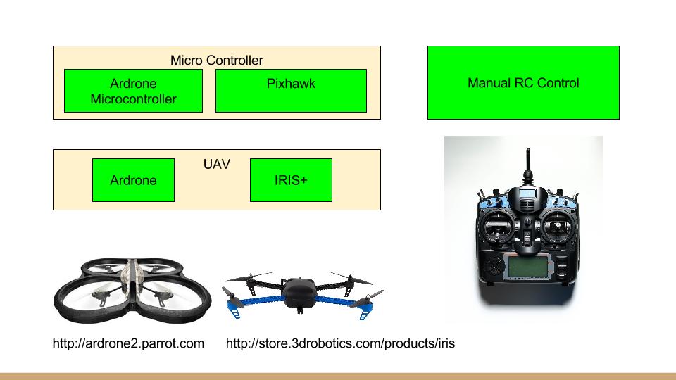
During the Fall semester, the low-level drone hardware was implemented and tested for both the AR.Drone and the Iris+.
During the Spring semester, the second set of hardware for the Iris+ was completed. This was used as a backup when there were breakages.
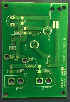
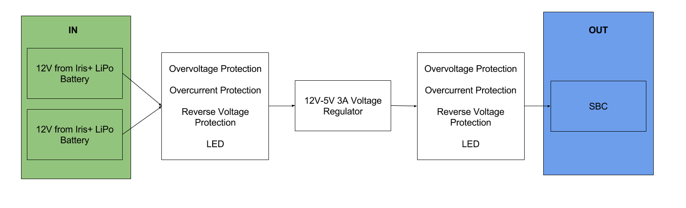
Power Distribution Board
The power distribution board was designed in order to be able to power an on board computer that takes 5V and 3A. The on board computer will be mounted to the Iris+ in order to be able to communicate with the Pixhawk flight controller. There is also power protection on the PCB in order to protect the on board computer from overcurrent, reverse current, and overvoltage. In order to facilitate hot swapping multiple batteries, multiple connections from the battery are supported.
The full specifications for the power distribution board are contained here: Power Distribution Conceptual Design
A general design chart for the power distribution board is shown below:
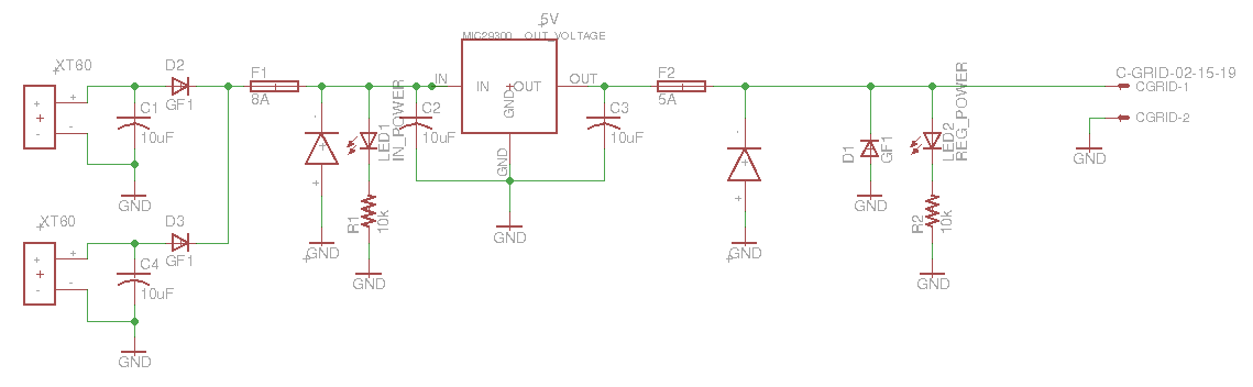
The schematic of the power distribution board is shown below:
The board design of the power distribution board is shown below:
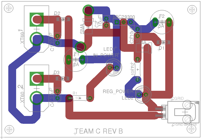
An image of the printed board is shown below: