Fall Validation Experiment
Test stage 1: Accurate AR.Drone2 Odometry
Success Conditions:
- Successful takeoff and hover of drone under manual control
- Drone autonomously completes 4 search sweeps of length > 4m each
- Drone path during search sweeps does not overlap with itself
- Drone successfully avoids contact with walls of B-level hallway
- Clear downward-facing video feed displayed during entire grid search process
- Full search process succeeds within 10 minutes of drone takeoff
Experiment Results:
During the FVE, the success criteria was defined in terms of speed, repeatability, robustness, and accuracy. The necessary success condition, as defined in our evaluation, are shown above.
The demo meet all the conditions successfully. During the demo, the drone took off under manual control. The user brings the drone to the proper height. The search sequence is initiated. The drone begins to sweep in its lawn mower search. It avoids walls and obstacles. In each sweep it takes a unique air route avoiding overlapping itself. Throughout the whole sweep process the drone streams video for the downward facing camera to a host computer. The full search without setup takes an average of two minutes. The drone sweeps four times through the length of the quarantined area.
A video of the lawnmower search can be shown below:
Test stage 2: Hardware Setup of Dock and Iris+ Drone
Success Conditions:
- Iris+ constrained within +/- 2 cm in dock (5 DOF)
- Valid orientation estimate and image (taken from the camera on the drone) is displayed on the PC
- ‘rostopic hz’ command shows > 0.1Hz on relevant topic on PC
Experiment Results:
For the prototype dock demo and the hardware-setup on Iris+, The demo needed to showcase the key functionalities of the the sensors, SBC and the high speed communication between the two and a host computer. The drone video orientation estimation must show valid orientation in roll pitch and yaw. The dock prototype needed to constrain the drone by its landing gear in 5 degrees of freedom. The necessary success condition for the hardware-setup and dock prototype, as defined in our evaluation, the were met were:
- Iris+ constrained within +/- 1cm in all directions by dock.
- Tighter than required +/-2 cm in dock (5 DOF).
- Valid orientation estimate and image (taken from the camera on the drone) is displayed on the PC
- Showcased the valid orientations: (Roll, Pitch, Yaw) = (90,0,0) and (0,90,0).
- ‘rostopic hz’ command command shows 1.09Hz for downward facing camera feed:
- Faster than required 0.1Hz on relevant topic on PC as specified in the requirements.
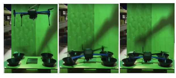
The dock also withstood a meter high drop test with the drone. The dock cones funneled the drones landing to the desired position. The landing gear combined with the dock cones absorbed a great amount the impact energy. This allowed for the drone to safely land with little abrupt impulse, protecting the sensitive components on its hardware.
The hardware setup on the Iris+ is shown below:
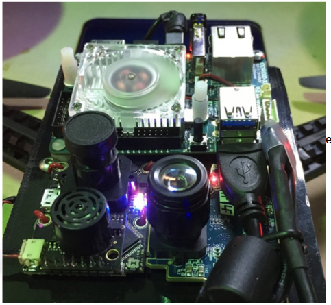
Hardware Setup
Images showing the dock test shown below:
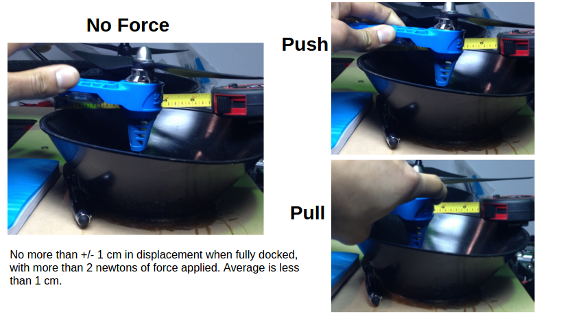
Docking Tolerance
An image of the drop test is shown below:
Manual Docking
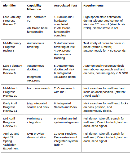
Test Plan
Schedule
Test Plan Schedule
Auxiliary Tests
Backup Iris+ Hardware Completed
The second Iris+ hardware was completed in early spring. We were able to fully get the software and hardware integrated. We were able to profile the speed of communication between the PIXHAWK Flight controller and the Odroid XU4 single-board computer.
A diagram of the communication is shown below.
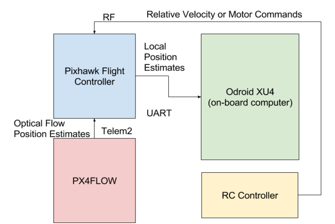
Communication System
The table below shows the frequency of the communication.
Communication Frequency
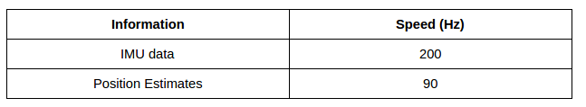
These update frequencies are what we expected and show that we can get reliable high speed communication between the PIXHAWK flight controller and the Odroid XU4 On-board computer.
April Tag Pose Estimate Filtering
Because of the high noise level of the pose estimates from the April Tag during pitching and rolling, we used a RANSAC filter to remove the outliers. The source code for the filter can be found here: https://github.com/ColumnRobotics/column/blob/master/src/BodyPoseFilter.cpp.
The following figure shows the output of the pose estimate before and after filtering.
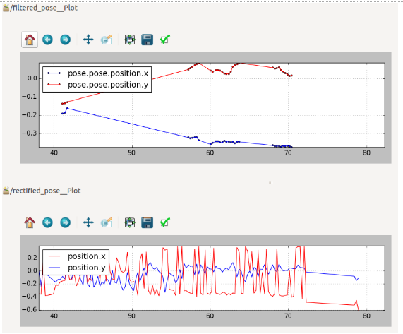
Pose Estimates Before and After Filtering
Spring Validation Experiment
Needed Equipment:
- Iris+ with mounted sensors and computer hardware
- wellhead
- dock
- caution tape
Operational Area:
25m2 in B – Level Basement
Test Process:
- Cordon off section of hallway
- Place wellhead at one corner of search area and dock 1m in front of the wellhead
- Place Iris+ on ground at opposite corner of search area facing wellhead within +/- 5 degrees
- Hit START button on PC to initiate sequence
- Manually take off Iris+, switch to OFF_BOARD mode, and begins searching for wellhead (marker)
- Confirm Iris+ arrives within 3 meter radius of wellhead
- Confirm Iris+ orients above dock in pre-docking position (within 1 meter of dock)
- Confirm Iris+ successfully lands in dock, constrained in 5 DOF
Success Conditions / Metrics:
Mandatory:
- Manually take off with Iris+ from ground
- Iris+ arrives within 3 meter radius of wellhead
- Dock with docking station, constrained in 5 DOF
Desired:
- Dock constraints 5 DOF
- Successfully avoid obstacles
Testing Conditions
Autonomous Hovering of Iris+
The Iris+ was shown to be able to autonomously hover around the April Tag even whenever the April Tag is being rotated. The Iris+ was servoed around the April Tag using the local planner we implemented (source: https://github.com/ColumnRobotics/column/blob/master/src/local_planner.cpp).
The figures below show the velocity updates from optical flow next to the position measurements whenever the Iris+ was hovering in place.
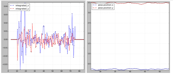
(Left) Velocity Measurements; (Right) Pose Estimates
Videos of the test is shown below.
Cone Search with Iris+
We implemented a PD controller to enable higher gains and damp the resulting oscillations. Figure 21 below shows the successful position and command velocity results of a square flight pattern with the new PD controller. The flight successfully followed the offset pattern (0,0) -> (+0.3, 0) -> (+0.3, +0.3) -> (0, +0.3) -> (0, 0) starting from the location (-0.28, 0.25) using a P gain of 4 and a D gain of 1. Command velocities peaked to +/- 3 m/s, but position is still able to quickly reach the target setpoint with minimal oscillation.
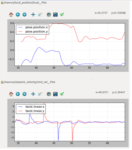
Square flight pattern under enhanced PD Controller
Position holding also exhibited very good stability with the new PD controller. As can be seen in Figure 22 below, we were able to maintain a very steady position of +/- 10cm over approximately 4 minutes.
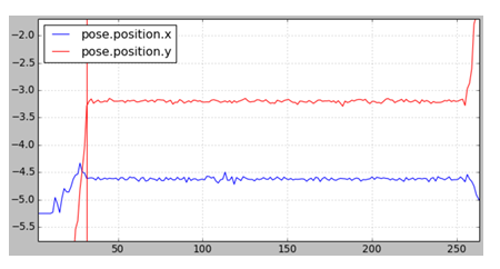
High-accuracy (+/- ~10cm) position hold over approximately 4 minutes
Docking
In order to accurately dock, we needed to be able to hover and land around the April Tag with high precision. The following figure shows our testing for precision landing.
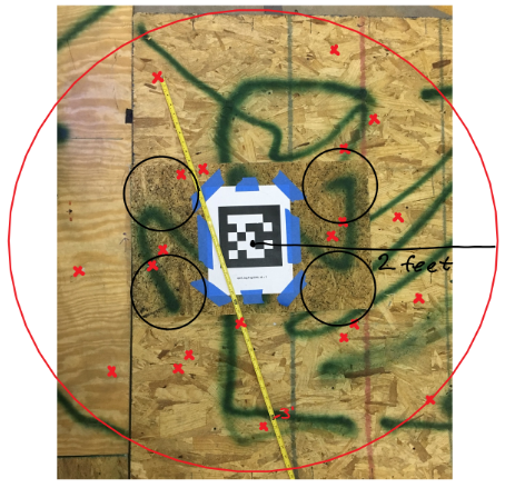
Docking Precision Tests
Each of the red X marks is a different landing point of the legs during one of our tests. As can be seen, we were consistently able to land precisely within two feet of the docking cones. And we were able to successfully land within the range of the cones a few times.
Final Integration
This system was fully integrated, and the full integration is implemented in the global planner, which is a bash file that can be found here: https://github.com/ColumnRobotics/column/blob/master/launch/global_planner.bash.
A video of one of the good landings can be found below.