Cyberphysical Architecture
Overview
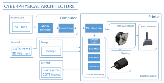
The cyberphysical architecture of the 4DOF system, shown in Figure, is inspired by the functional architecture and standard 3D printers. It comprises a software component, namely the ADDIN Software, Skeinforge Slicer and the printer interface, and a hardware component which is the 4DOF printer.
The 4DOF system is based on the Makergear M2 commercial 3D printer that was provided by our sponsor and already contains many of the necessary system components. The remaining portions of the cyberphysical architecture which are being developed by the ADD_IN team are:
- ADDIN software: Our custom made software, that uses the Skeinforge Slicer to generate a standard 3DoF G-code and then computes and adds the 4th DoF.
- The printer controller: The Arduino based RAMBO Board for which we modified the Firmware to enable control of all degrees of freedom.
- R axis joint: To avoid collisions while printing around the perimeter of COTS items the extruder nozzle must be infinitely rotatable. To enable infinite rotation a slip ring transfers heater power and temperature signals across the joint.
- Angled Nozzle: A custom nozzle capable of printing along the surface of the COTS item
These components are explained in more details in the subsystems section of this report.
Description
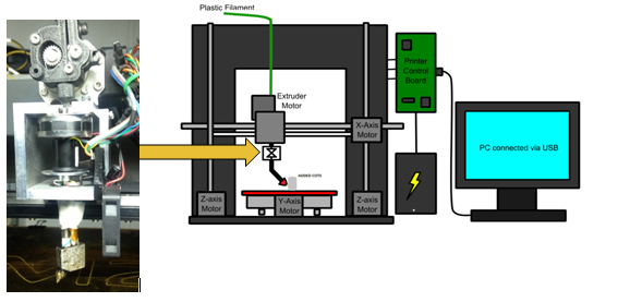
Figure provides a graphical illustration of the 4DOF printer. The components on the left describe how the nozzle and rotation joint will be physically mounted on the 3D printer.
Many of the components in the cyberphysical architecture are from the original unmodified 3D printer. The main modification is highlighted in Figure where it is shown how the hollow shaft stepper motor and the slip ring are mounted on a metallic mount that was machined in-house. The new mount provides support for the fan, encodes wheel and optical-sensor, and also comprises a bearing to reduce the flexibility of the nozzle.

