Software Subsystem
1. Framework
The software framework was built to be robust by employing OOPS concepts that allowed smooth handling of data. The subsystem employs the use of three Classes: ADDIN, PrinterState and COTSItem
PrinterState
The class PrinterState binds all the state variables related to one G-Code command together. These include the XYZR positions of the motors, temperature of the extruder and bed, speed, extrusion rate, etc. With the help of this class, we are able to read G-Code line by line, translate all the state variables into an object of class PrinterState and hence create a table as shown below. Once all the G-code has been read and converted to an array of states, we are free to process the data without having to deal with the .gcode file.
Table 4: G-Code represented in tabular format
| Index | GCommand | X | Y | Z | R | E | F | Tbed | TNozzle |
| Obj 1 | ‘G01’ | 2.434 | 1.876 | 1.5 | 30 | 10 | 1800 | 60 | 215 |
| Obj 2 | ‘G01’ | 4.234 | 4.764 | 1.5 | 30 | 15 | 1800 | 60 | 215 |
| Obj 3 | ‘G01’ | 5.876 | 8.764 | 1.5 | 30 | 20 | 1800 | 60 | 215 |
| … |
ADDIN
The ADDIN class contains all the data and functions pertaining to one particular 3D part. Some of the functions it includes are:
- Read G-Code file into array of PrinterStates
- Compute R axis commands
- Plot the 3D part
- Write PrinterStates back into a .gcode file
COTSItem
An object of this class represents all the data related to one COTS item, which includes its dimensions, minimum and minimum z heights, etc.
2. Path Planning Algorithm
Description:
The path planning algorithm essentially computes the angles that the stepper must rotate by during the execution of each G-Code command in order to stay clear of collisions with the COTS part.
The basic steps for the algorithm are as follows:
- Orient the printer nozzle to be normal (or at some specified angle) to the velocity trajectory of the nozzle at all times (this yields two possible solutions for nozzle orientation).
- Always orient the nozzle to be pointing towards the nearest COTS item (this selects between the two solutions in (1)).
In this design the path planning algorithm simplifies each COTS item to a ‘keep out’ zone centered at a specific point location and with a specified height. The assumption is made that the G-Code file for the printed part is designed to accurately represent the exterior profile of the COTS item, and thus no other information is needed about the COTS item’s external geometry. Not relying on additional geometry information implies that the part designer avoided creating a design which violate the geometry constraints of the printer (i.e. parts are too close together, or have concave profiles that the nozzle cannot access), since these potential collisions will not be detected by the path planning algorithm.
The path planning algorithm was implemented in MATLAB and is applied to a given G-Code file. The inputs to the algorithm are a G-Code file produced by Slic3r which encodes the XYZ locations the print nozzle must move to, and a list of COTS item locations and heights. Using this information, the algorithm computes the necessary angle of the rotation axis for each G-Code movement command, and produces a modified G-Code file. It was discovered that Skeinforge only produces straight line commands (G00 and G01) which greatly simplifies the implementation algorithm because rotation along an arc doesn’t need to be considered.
An example of the modified G-Code is shown below:
g1 x119.200 y133.151 e1238.61271 r18.4349
g1 x118.973 y133.665 e1238.63294 r90
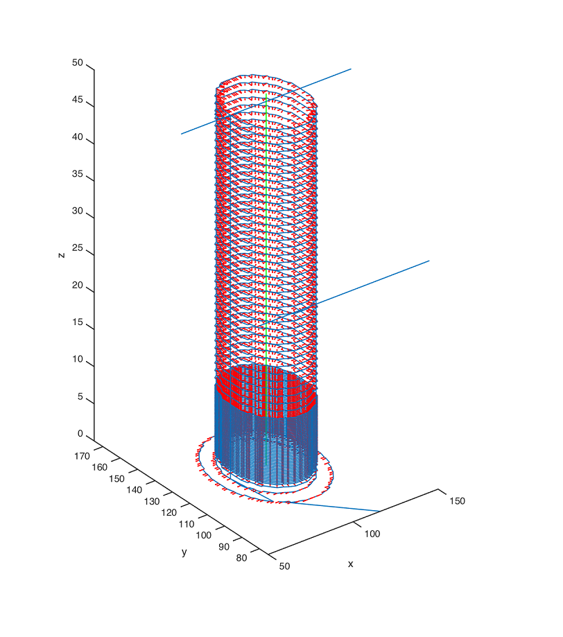
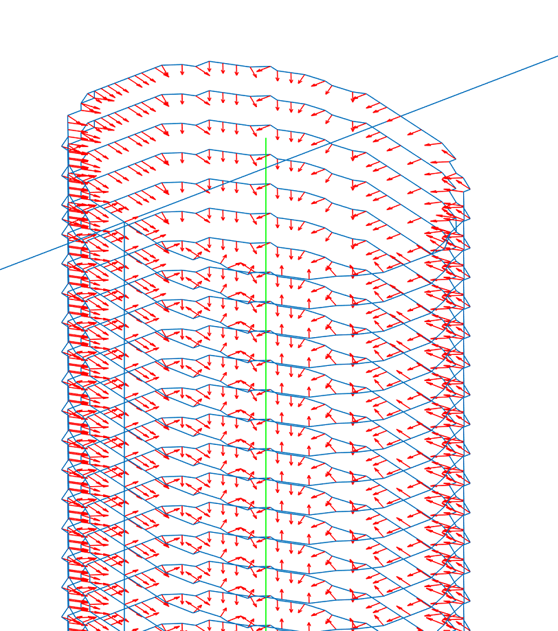
The figures below show the R-Axis commands generated for a cylinder with a rod placed inside it as a COTS item. As we can see, the arrows are all pointing towards the center, thus orienting the nozzle to not collide with the COTS item. The results clearly indicate that the algorithm is successfully controlling the nozzle orientation to avoid collision with the COTS item.
3. Graphic User Interface
The GUI ties together all the functions written in the software and provides the user with an easy to interpret application that takes care of the special G-Code generation from start to end.
The process can be understood by the following images:
|
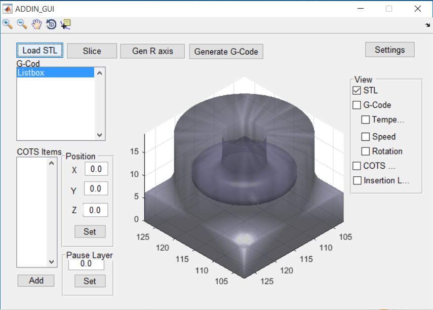
Visualization of STL file in GUI |
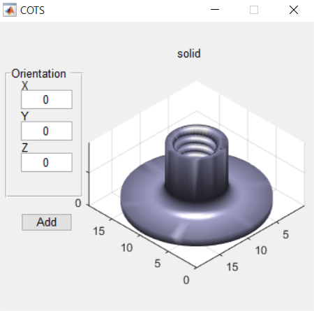
Addition of COTS item (with options to vary orientation) |
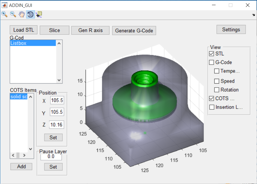
Positioning of COTS item within 3D part
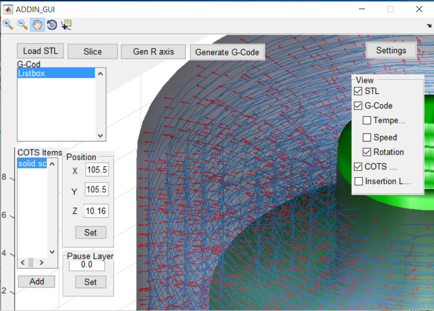
Visualization of R-Axis commands per G-Code
4. Settings Window
The settings window is an extremely useful functionality of the GUI that allows the user to define the commands used to invoke the slicing software locally. This makes the software completely portable and also eases the process to save settings.
As shown in the figure below, the Settings Window lets the user specify the following settings:
- The location of their slicing software on their system locally
- Slice Settings which vary from print to print
- Command to invoke the slicing software from command line
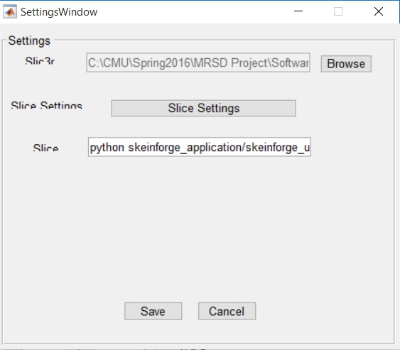
Settings Window
The settings window came in handy when the project required us to shift between slicing software in the last minute. When the previously employed ’Slic3r’ started causing problems, we switched to ‘Skeinforge’ which allowed us to tune many more setting, giving us more room to obtain high quality prints. The three settings mentioned above were all we had to change in order to make this transition from Slic3r to Skeinforge.