Microcontroller Subsystem
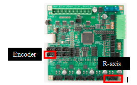
The microcontroller board that powers the Makergear M2 is the RAMBo 1.1B Controller Board. Rambo stands for RepRap Arduino-Mega Board. As shown in Figure. the Rambo board is an all-in-one electronics board that communicates with the printer interface software via USB and is used to control all components of the 3D printer.
Firmware
The board on our Makergear 2 is loaded with the Marlin Firmware, which is Arduino based and entirely open-source. The role of the Firmware is to interpret the G-code commands and control the printer’s heaters and motions accordingly. The firmware has been extended to control a 4th degree of freedom which is the rotational axis. The rotational axis combined with above designed nozzle is used to avoid colliding with the COTs item and also improve the quality of print. To ensure that the print is as per the G-code the firmware incorporates the kinematics and inverse kinematics of the nozzle tip.
Modeling, analysis, and testing
Electrical Connections
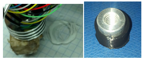
The rotational axis is controlled using a stepper motor through the RAMBo board. A hollow stepper motor has been used as described above. To align the rotational axis and assign a homing to the R-axis we use an encoder wheel assembly with and optical encoder. The optical encoder is connected to the limit switch port. Figure shows the Rambo board extended connections used by ADD_IN.
Kinematics and Inverse Kinematics
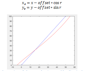
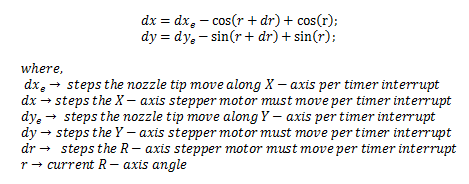
All the axes in the original firmware are moved synchronously with constant velocities. The x-axis and y-axis are moved in a straight line. This results in the extruder tip moving along a curve as shown in Figure. So, I worked out the inverse kinematics for the x and y location such that the extruder tip moves along the required straight line. The following are the equations for the inverse kinematics:
Based on the above equations the velocities for the stepper motors are calculated so that the synchronous movement results in a straight line. The velocities of the stepper motor are defined as follows:
To implement the above equations a look up table was implemented which consists of the trigonometric values. These were stored as integer values scaled to an appropriate magnitude so that all the computations could be performed quickly in the interrupt service routine. The implementation had drift issues which were solved by increasing the resolution of the computations. Figure shows the initial drift and the correct prints after solving the drift issues.