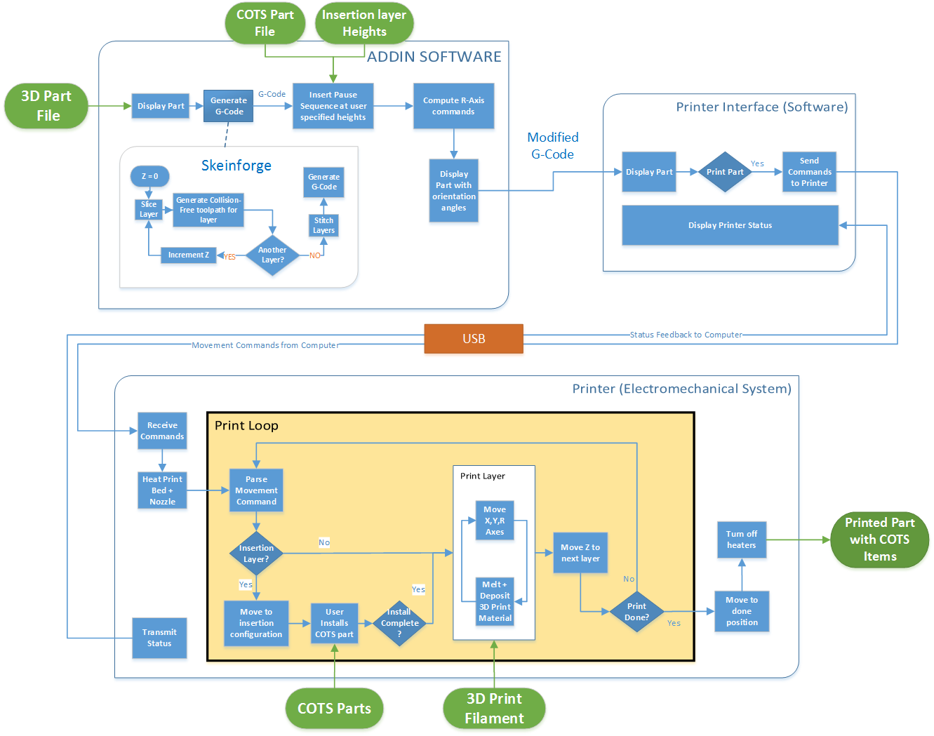
1.1 Slicing Software
This subsystem is responsible for generating the G-Code that is fed to the printer. G-Code consists of a list of coordinates that define a path the printer nozzle must navigate while depositing the print material. The following is an example of a G-Code command. It includes a positioning command ‘G00’ followed by coordinate locations for the XYZ axes.
G0 X0 Y0 Z0.25
The subsystem was developed into an easy to use GUI. The user is allowed to select the STL file of the part to be printed. This part is then sliced to generate G-Code for the three existent XYZ axes by invoking a slicing program called ‘Skeinforge’ from command line. The user can vary the settings for the print, such as the layer height, infill pattern, extrusion rate, etc. Once the basic settings have been decided and G-Code generated, the user can select the STL file of the part to be inserted inside the printed body and position it in place by entering its XYZ position and orientation. After locking the COTS part in its correct location, the user must enter the insertion height at which the printer will pause to allow the COTS insertion. Based on the position of the inserted part, the obtained G-Code is modified to include the R-axis commands, which are nothing but the angle by which the 4th stepper motor should rotate during the execution of each G-Code. The R-Axis movements ensure that the body of the nozzle and heat block do not collide with the COTS item.
This subsystem finally generates G-Code complete with commands to drive all the motors. This G-Code is then loaded into the printer interface to be fed to the printer line by line.
1.2 Printer Interface Software
The printer interface loads the G-Code generated by the slicing software and displays the 3D sliced model on the computer screen. It communicates with the microcontroller mounted on the printer over USB. The microcontroller receives instructions to initiate the print when the user hits ‘Print’. While printing the interface streams G-Code commands to the printer, and the status is transmitted back from the printer to the software. The print status is displayed on the screen, giving the user real time feedback on the print progress.
1.3 Printer (Electromechanical System)
The printer is an electromechanical system that is responsible for physically producing the required 3D assembly. A soon as the microcontroller on board receives commands to initiate the print; it first begins to heat the bed and nozzle head to temperatures defined in the G-Code. The printer then begins printing the base structure layer by layer. If and when it encounters an insertion layer, the hot nozzle moves to the safe configuration and alerts the used to place the COTS item in its feature. The user then inserts the item and hits ‘resume’ which causes the nozzle to go back to its printing temperature and continue printing. Aided by the bent nozzle, extra degree of freedom and computed R-axis commands, the nozzle is able to smoothly enclose the added part in print material. Once the print had been completed, the heaters are turned off and the bed is rolled out to display the finished 3D part.