Nozzle Subsystem
Description
The original nozzle on the Makergear M2 can only print parallel to the print bed. To print along the surface of COTS items a custom nozzle which can extrude filament at an angle is required. The nozzle subsystem describes the entire assembly which is required to melt and deposit filament including a mounting interface, heater, heat block, thermal insulator, thermistor, and small diameter brass nozzle.

Status
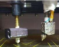
A custom nozzle was designed and manufactured to meet the system requirements. Multiple iterations and adjustments were performed to achieve a reliable nozzle with correct thermal and mechanical properties. Operation of the nozzle was demonstrated throughout the spring semester, and especially the SVE. A representation of the original and modified nozzle system is shown in Figure.
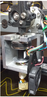
The final iteration of the nozzle features a 30 degree bend, thus giving it the clearance to print on surfaces that are orthogonal to the print bed. Figure . below shows the actual nozzle that was machined as per the nozzle design. This proved to be the most reliable one, the 30 degree angle and smaller aperture angle enables the nozzle to have a larger angle with respect to the print bed and not smudge the filament. The thinner heat block enables easier collision free planning with cots items.
Analysis
The nozzle was tested extensively to determine the correct operating parameters (temperature, print speed, nozzle diameter, nozzle angle, fan setting) that produces the best print quality. After many issues, especially jamming and smudging, the final iteration produces very reliable printing; the jams were resolved thanks to better heat transfer control, using a fan, insulator, and heat sinks. And the filament smudging is mitigated by reducing the nozzle aperture angle and the heat blocks bend angle.
Rotary Joint Subsystem
Description
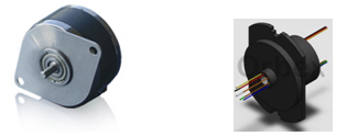
The rotational joint subsystem is the mechanical portion of our system that provides an additional degree of freedom to the 3D printer necessary to avoid collisions with COTS items. The components of this subsystem are the stepper motor, the slip ring and the mount. Figure shows a picture of these components.

The main design objectives for this subsystem were to minimize weight, flexibility and backlash, while maintaining a small form factor (especially the height as it will result in reduced print volume), and to satisfy our performance requirements for speed and precision. These are the main aspects that guided the selection of the components.
Analysis
Stepper motor
The motor we used is the 3709 stepper motor from Lin Engineering, custom made to have a hollow shaft. The specifications of importance for our system are as follows:
Repeatability: 1.5 % of a step = +-0.0135°
Holding Torque: 0.04 N-m
Weight: 80 grams
Steps per revolution: 400
Hollow shaft ID: 3 mm
Also the stepper is compatible with the A4988 stepper driver that is on our control board.
Slip ring

For the slip ring, we also needed a compact and lightweight component with at least 5 power lines, low added noise and hollow shaft. We selected the 504-0800 from Orbex, which satisfies these requirements. Figure shows the stepper motor and slip ring.
Mount
The mount was machined in-house to host all the rotary joint components, namely the stepper motor, slip ring, fan, encoder wheel and optical sensor and to connect with the hot end (bottom) as well as the filament drive(Top). A previously 3D printed version had some flexibility in the nozzle so we machined a metal version that also has a bearing to make it more rigid, the result is very rigid and reliable. Also the mount is directly mounted on the X-carriage, and the extruder motor lifted about 6cm higher, that was done by design in order to preserve the print volume, i.e. in this version the maximum print height is only reduced by 4cm.