First PDR Board
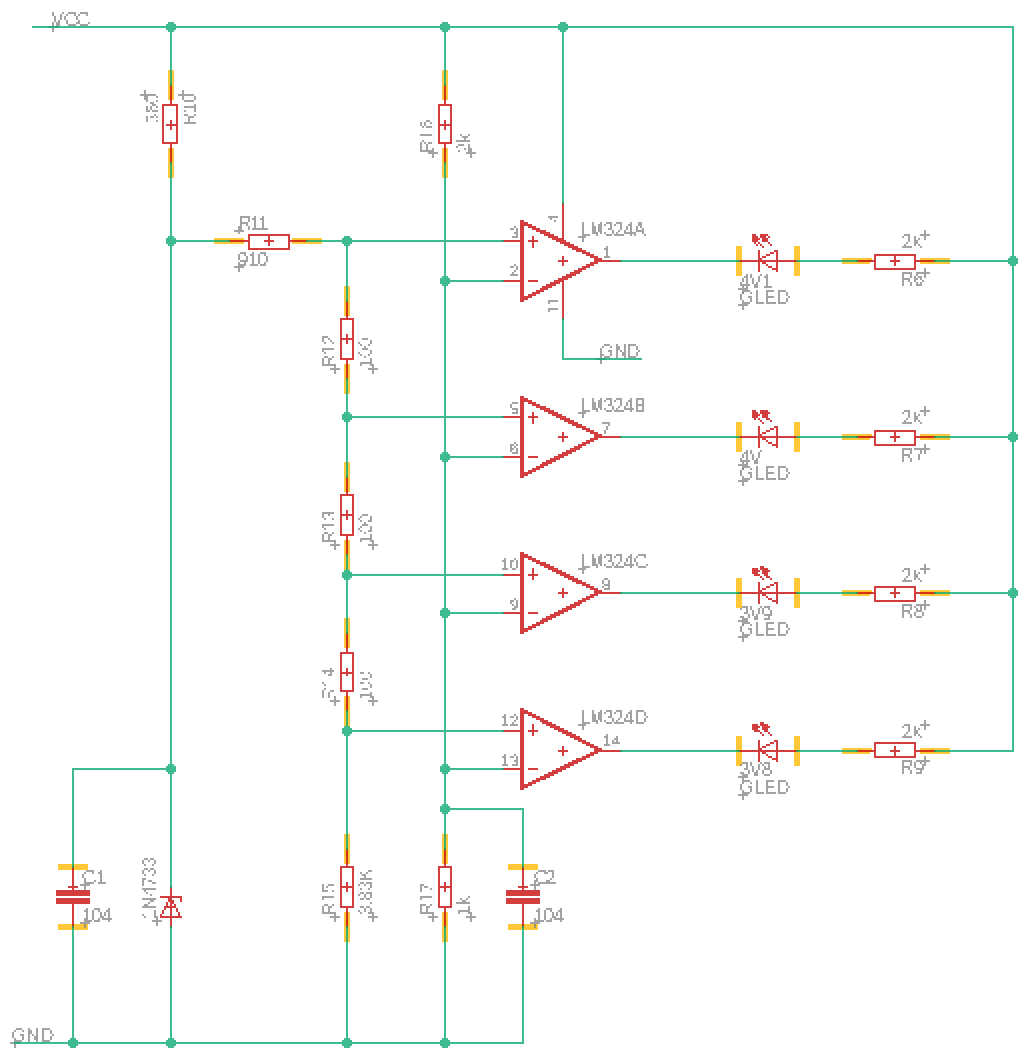
Schematic Circuit Diagrams:
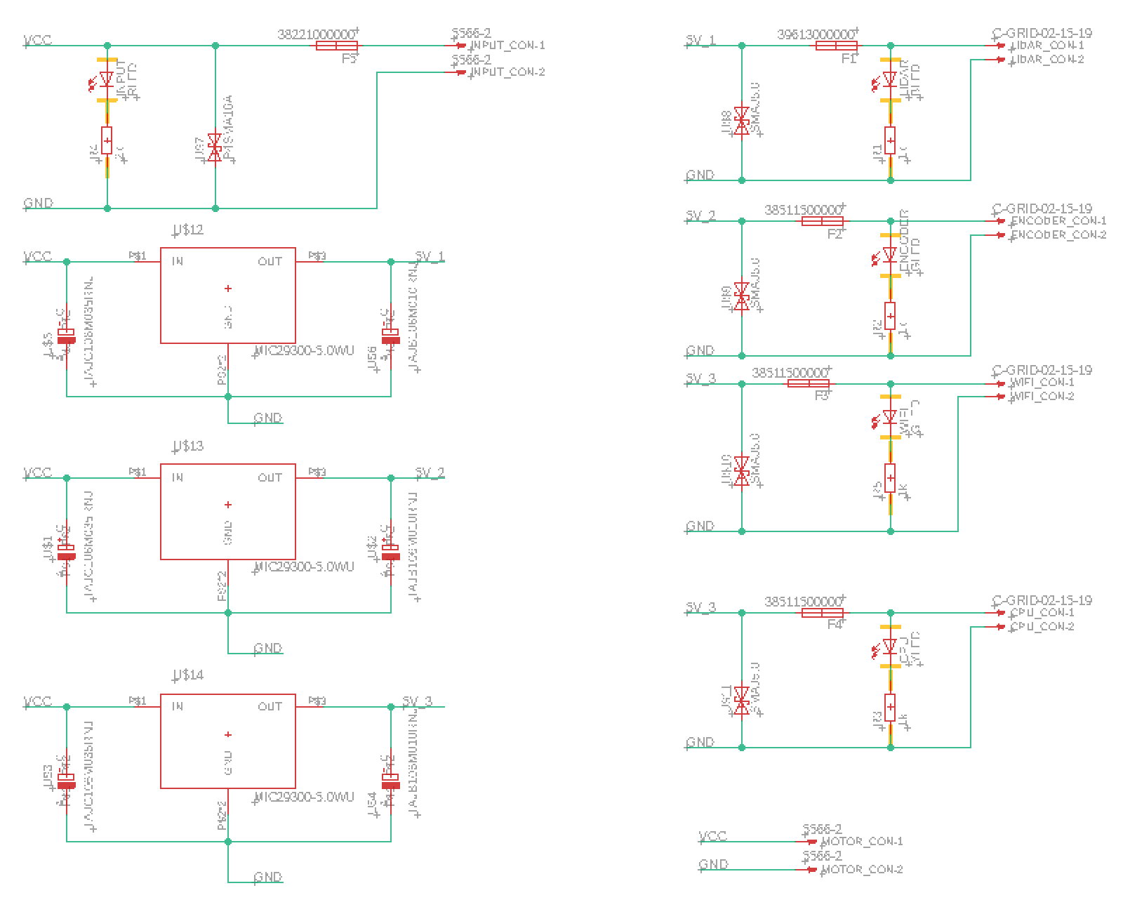
Calculations:
1. State the efficiency of each of your regulators.
Regulator 1:
3.3V/24V = 13.75%
Regulator 2:
5V/24V = 20.83%
Regulator 3:
12V/24V = 50%
2. State the input power used for each subsystem at the maximum rated output.
CPU subsystem:
P_in = P_out/η = (I_out*V_out)/η
= (3.3V*1A)/13.75%
= 24 W
Wifi & encoder subsystem:
P_in = P_out/η = (I_out*V_out)/η
= (5V*1A)/20.83%
= 24 W
Lidar subsystem:
P_in = P_out/η = (I_out*V_out)/η
= (12V*2A)/50%
= 48 W
Motor subsystem:
P_in = P_out = I_out*V_out
= 24V*10A
= 240 W
3. State the total system efficiency at maximum rated output.
η_total = P_out/P_total
= (3.3V*1A+5V*1A+12V*2A+24V*10A)/(24W*2+48W+240W)
= 272.3W/336W
= 81.04%
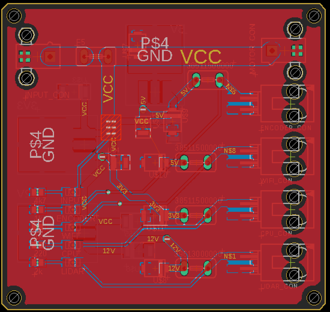
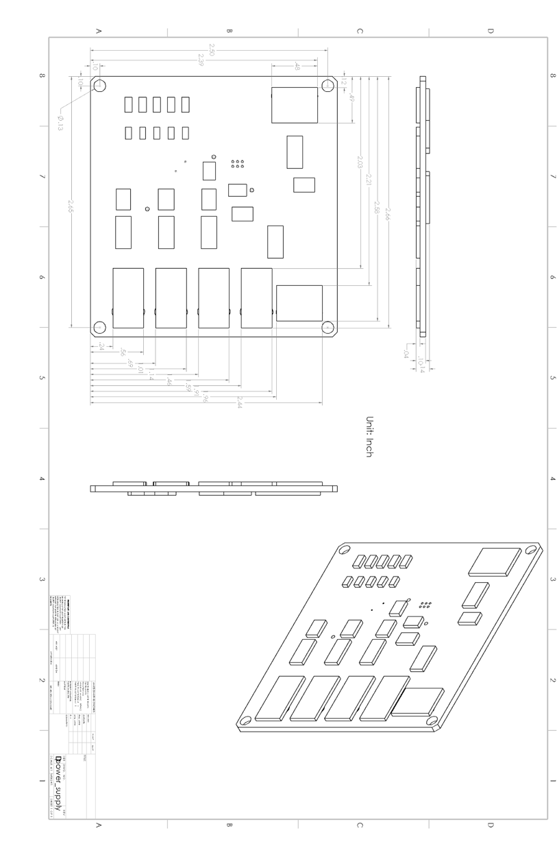
PCB Layout:
Second PDR Board
In our system, as we plan to distribute several wireless temperature sensors in our test field to collect ground truth data, we need to power three WiFi gateways that connect to ground truth sensors to read the ground truth data. Apart from the three WiFi gateways, we also need to power a RTK GPS base station that helps UAV get higher localization accuracy.
These systems are powered by a Li-Po Battery for its portability and the detailed description of the systems and the power source including voltage range, continuous current, the regulation requirement is listed in the following table.
Table 1. Power sources and Subsystems list
|
Power source/ subsystem to be powered |
Specifications | Voltage range | Continuous
Current |
Peak Current | Regulation required? |
|
WiFi Gateway to access ground truth temperature sensors |
DC 5V 2A |
DC 5V |
2A | Not listed | Yes |
|
RTK GPS Base Station |
DC 5V
35mA |
DC 5V |
35mA |
Not listed |
Yes |
| Li-Po Battery | 3 Cells
3.7-4.2V for each cell |
DC 11.1V – 12.6V | 218 A |
Not listed |
– |
Schematic Circuit Diagrams:
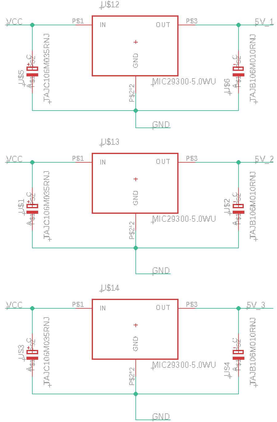

![]()
![]() Efficiency Calculation:
Efficiency Calculation:
Input Voltage: 12V (3-cell LiPo battery, 11.1V ~ 12.6V)
Wifi Gateway Subsystem:
Efficiency: 39.7%~45.0%
Output Voltage: 5V
Continuous Output Current: 2A
RTK GPS Subsystem:
Efficiency: 39.7%~45.0%
Output Voltage: 5V
Continuous Output Current: 35mA
Heat Dissipation Calculation:
1. For the WiFi gateway subsystem regulator:
Ground current ~1% I_out
Thermal Resistance TO-263: θ_JC = 2°C/W
Max operating junction temperature T_Jmax = 125°
Power dissipation:
P_D = I_out(1.01(V_in-V_out)) = 2A(1.01*(12V-5V)) = 14.14W
Junction temperature:
T_J = (θ_JC*P_D)+T_A = 2*14.14W +25 = 53.28°C
T_J < T_Jmax
2. For RTK GPS Base Station subsystem regulator:
Ground current ~1% I_out
Thermal Resistance TO-263: θ_JC = 2°C/W
Max operating junction temperature T_Jmax = 125°
Power dissipation:
P_D = I_out(1.01(V_in-V_out)) = 0.035A(1.01*(12V-5V)) = 0.2475W
Junction tempreture:
T_J = (θ_JC*P_D)+T_A = 2*0.2475W +25 = 25.495°C
T_J < T_Jmax
PCB Layout: