Spring Validation Experiments
Test 1: Master Computer Subsystem Validation Experiment
| Objective |
To validate the correctness of the modeling and sampling algorithm. |
| Location |
No specific requirement. |
| Equipment |
Master Computer, Intel Lab Data [9] |
| Procedure |
- Master computer updates temperature model.
- Master computer determines next interest points.
- Master computer allocates corresponding interest point to each robot.
- Directly return temperature data from Intel data set.
- Loop through procedure 1 – 4 until temperature model converges.
- Computer root mean square error between the generated model and ground truth temperature distribution.
|
| Requirements |
- The root mean square error is less than 1 ℃.
- UGV and UAV are never allocated to the same point.
- Temperature model converges within 50 loops.
|
Test 2 & 3: UGV/UAV Subsystem Validation Experiment
Note: The test design is the same for UGV and UAV. We will perform one test for each robot.
| Objective |
To validate the correctness of UGV/UAV subsystem. |
| Location |
A 20m x 20m x 5m outdoor area behind the NSH hall |
| Equipment |
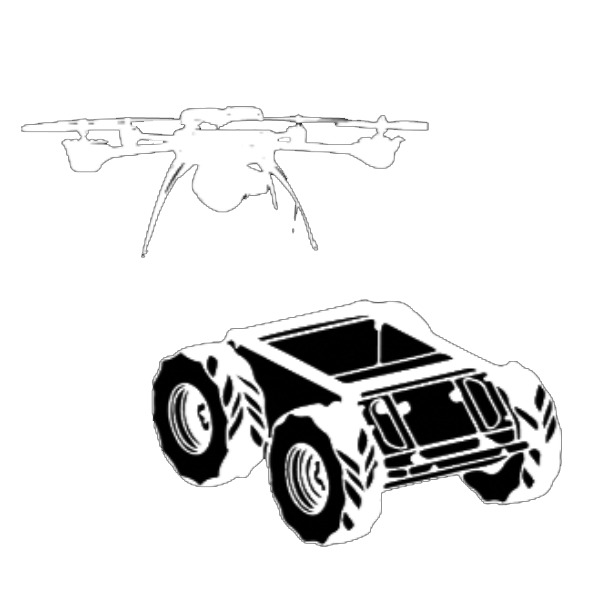
Jackal UGV/ AscTec Pelican UAV, Tape measure, Temperature sensor, Stopwatch |
| Procedure |
- Power on Jackal UGV/ AscTec Pelican UAV.
- Assign a target location within the test field to Jackal UGV/AscTec Pelican UAV.
- Jackal UGV/AscTec Pelican UAV autonomously moves to the target location.
- Jackal UGV/AscTec Pelican UAV stops when it localizes itself close enough to the target location.
- Jackal UGV/AscTec Pelican UAV takes and reports temperature sample.
- Loop step 2 – 5 ten times and measure location error between Jackal reached position and the target position, and temperature error between Jackal’s measurement and ground truth temperature at each time.
|
| Requirements |
- Mean location error is less than 2 meters.
- Mean temperature error is less than 2 ℃.
|
Fall Validation Experiments
Integrated System Validation Experiment
| Objective |
To validate the correctness of the whole system. |
| Location |
A 20m x 20m x 5m outdoor area behind the NSH hall |
| Test Field |
A 20m x 20m x 5m area with designed obstacles randomly placed. 3 – 5 heat sources are also placed within the test field to increase temperature distribution variation. |
| Equipment |
Master Computer, Jackal UGV, AscTec Pelican UAV, Tape measure, Temperature sensor, Stopwatch, Heat source. |
| Procedure |
| 1 |
Manually collect 100 temperature samples within the test fields to build a ground truth temperature distribution. |
| 2 |
Master computer updates temperature model |
| 3 |
Jackal UGV asks master computer for the location of next interest point. |
AscTec Pelican UAV asks master computer for the location of next interest point. |
| 4 |
Master determines the next interest point for Jackal UGV. |
Master determines the next interest point for AscTec Pelican UAV. |
| 5 |
Master computer sends the next interest point to Jackal UGV. |
Master computer sends the next interest point to AscTec Pelican UAV. |
| 6 |
Jackal UGV autonomously moves to the target location. |
AscTec Pelican UAV autonomously moves to the target location. |
| 7 |
Jackal UGV stops when it localizes itself close enough to the target location. |
AscTec Pelican UAV stops when it localizes itself close enough to the target location. |
| 8 |
Jackal UGV measures temperature and report it to master computer. |
AscTec Pelican UAV measures temperature and report it to master computer. |
| 9 |
Loop through procedure 3 – 8 simultaneously for Jackal UGV and AscTec Pelican UAV until the temperature model converges. |
| 10 |
Computer root mean square error between the generated model and ground truth temperature distribution. |
|
| Requirements |
- The root mean square error is less than 3 ℃.
- UGV and UAV never collides with obstacles or each other.
- Temperature model converges within 50 loops.
|
