This page contains specific information about each subsystem. The description and graphical depiction of our full system design can be found here.
Virtual Robotic System
Simulation Subsystem
The simulation subsystem replaces the real world to inexpensively analyze effects on multiple robots in an industrial environment. We plan to use a 3D simulator commonly used for robotics: Gazebo. Robots will be provided with a static floor map, goal waypoint locations, localized ego position, and ego pose estimation. A Gazebo-compatible environment model will emulate the industrial environment, and Gazebo will be run at runtime to accommodate the associated subsystems below. The simulation will also simulate trajectories for dynamic obstacles.
Alternatives: If Gazebo is too computationally expensive or difficult to implement, we will deploy the simulation computation to the cloud and visualize locally.
Path Planning Subsystem
The path planning subsystem handles the generation of the nominal path that the robots will follow, given the environment floor map, the start position, and the goal positions. This subsystem would not consider dynamic objects, and so essentially solves a static path planning problem, which can easily be solved by standard methods such as A*. In our trade studies, we found a version of A* (“Remodeled A*”) which is modified to suit mobile robots, that we can employ for this subsystem.
Alternatives: If the modified A* algorithm does not work well, there are numerous static path planning algorithms that we can utilize, such as probabilistic roadmap methods or Djikstra’s method.
Object Tracking Subsystem
This subsystem will handle the simulated object detection and classification, and will use the results from physical object tracking tests. To model the physical object tracking performance in simulation, we plan on taking ground truth data and adding additional Gaussian noise to the bearing and range of the obstacles in the robot frame. Any obstacles that are occluded, outside of the field of view, or beyond a certain range will not be provided to the robot.
Alternatives: We could instead add Gaussian noise to the Euclidean position of the obstacles in the robot frame.
Prediction and Avoidance Subsystem
The prediction and avoidance subsystem is critical, as it includes the algorithms the robots will use to avoid collisions. As we discovered through trade studies, the algorithms that best fit our specific system requirements are “Trajectory-based Motion Prediction” which uses a “Trajectory Dictionary” to store past observed trajectories to inform obstacle motion predictions, “Clearance-Based Probabilistic Roadmap Method” (CBPRM) and “Socially Aware Limit Cycles” (SALC) which innately maintain distance margins to obstacles, and “Optimal Reciprocal Collision Avoidance” (ORCA) which uses observed velocities to allow non-communicating robots to avoid collisions amongst themselves. Altogether these algorithms will allow the robots to handle a wide range of collision scenarios, regardless of whether obstacle classification and prediction is confident or not.
Alternatives: If we find that these algorithms do not work well for our purposes, we can instead use different algorithms that have similar functionalities. For predictive avoidance, we can use Kalman Filter or curve fitting approaches to predict based on past observations. For non-predictive avoidance, rapidly exploring random tree (RRT) methods could be used instead. For collisions between robots, if the ORCA method fails we can allocate more resources to improving our non-predictive avoidance algorithm so that it can handle these interactions.
Control and Mobility Subsystem
This subsystem will handle motion of the simulated robots. The robots will be actuated using software commands within our chosen simulation software, allowing for the velocity of the robots to be set while conforming to the given physical constraints. To control the paths of the robots we will use differential drive robot kinematics with LQR or PID control (available as a ROS package).
Alternatives: If necessary, we may instead use alternate path tracking algorithms such as pure pursuit.
Visualization Subsystem
For debugging, testing and demonstration purposes, the visualization subsystem will use RViz to plot both the historical trajectories and future waypoints for each robot as well as historical and predicted trajectories for the obstacles on the map at runtime. It will also plot and record the productivity curves versus time with rqt_graph, to evaluate the performances with different avoidance algorithms.
Alternatives: If necessary, we may use an alternate visualization tool: WebViz. Or, if we fail to implement real time visualization with RViz and rqt_graph, we could create custom visualization software in Python.
Command Module Subsystem
The command module subsystem handles the input of goal waypoints to the simulated robots in the form of locations in the given environment floor map. This will be implemented through software commands in the simulation software, where the positions of the waypoints are manually inputted.
Alternatives: Instead of manual input, goal waypoints could be taken from a predefined list. This may be easier to implement, though may reduce control during testing.
Real-life Robotic System
Data Acquisition Subsystem
The data acquisition subsystem includes two sensors: a camera and a 2D LiDAR. The camera will be used to capture semantic information of the environment through a video feed. The 2D LiDAR, included in the TurtleBot robot base, outputs a 360-degree 2D point cloud that specifies the distance between the sensor and surrounding objects through the use of a time-of-flight sensor. Combined, the images in the video feed and the 2D point cloud allow the robot to estimate the location and class of each obstacle in its view. The two sensors will be mounted close to each other and vertically aligned, to aid sensor fusion.
Alternatives: When the above two sensors are not sufficient to provide good data for classifying and localizing obstacles, the 2D LiDAR could be changed to a dense 3D LiDAR that has higher resolution and can provide additional semantic information for classification, but at the cost of higher price and more difficult integration/fusion.
Detection & Classification Subsystem
In the detection & classification subsystem, the software component for processing camera data is YOLOv4, which is an object recognition system based on a convolutional neural network. It accepts images as input and outputs object’s bounding boxes and classes. In the real-life system, YOLOv4 will be trained to recognize obstacles of interest in the project, such as forklifts and pedestrians.
The data outputted by the LiDAR is a 2D point cloud surrounding the sensor. There are many approaches to fuse the data from the camera and LiDAR; one simplistic way is to project the LiDAR data onto the camera image and look for overlaps between the point clouds and bounding boxes. This is equivalent to slicing LiDAR data in the same yaw orientation as the bounding boxes in the camera image. However, this approach requires the LiDAR and camera to be aligned vertically, and somewhat relies on the accuracy of bounding boxes. After the position of each obstacle is determined, the subsystem will output a list of obstacles with their classes and positions.
Alternatives: The main challenge of this subsystem is recognizing obstacles of interest from images quickly. Should YOLOv4 fail to achieve this goal, an alternative way to easily classify obstacles would be scanning barcodes (such as ArUco markers) placed on obstacles beforehand. This is somewhat feasible in the context of this project since the obstacles of interest are industrial vehicles or personnel. Still, in practice barcodes can be unreliable as they’re often damaged or lost in daily operation. Applying barcodes on thousands of industrial vehicles and pedestrians in a factory is also a huge logistical cost.
Ground Truth Subsystem
The ground truth subsystem is responsible for gathering the robot and obstacles’ positions to compare the estimation from the robot with. This subsystem gathers ground truth using an overhead camera that tracks markers (colored dots or barcodes) placed on top of the objects in the testing area, including the robot and obstacles. The camera will be mounted as high as possible to reduce offset error caused by the objects’ heights and camera projection. Detection of markers can be handled by existing libraries reliably. The ground truth pose of the robot gathered using this method will also be used to convert the robot’s estimation of obstacle positions from the robot coordinate frame to the world coordinate frame, so that they may be compared with ground truth obstacle positions. One thing we should also consider for this subsystem is scaling objects and environments. The scaling between actual factory objects and our real-life system will be around 1:10. To simulate this scaling with our Turtle bot, we will mount the sensors very low to the ground on the Turtle Bot. Also, given the 1:10 scale and the 18m detection requirement, the real-life system perception range should be 1.8m. To make testing more convenient and flexible, the testing area is chosen to be a 2m x 2m square. The height of the camera mounting depends on the camera’s vertical FOV. Given the camera’s FOV and testing area width d, the minimum height should be. The images below illustrate the proposed setup for ground truth gathering and example markers:
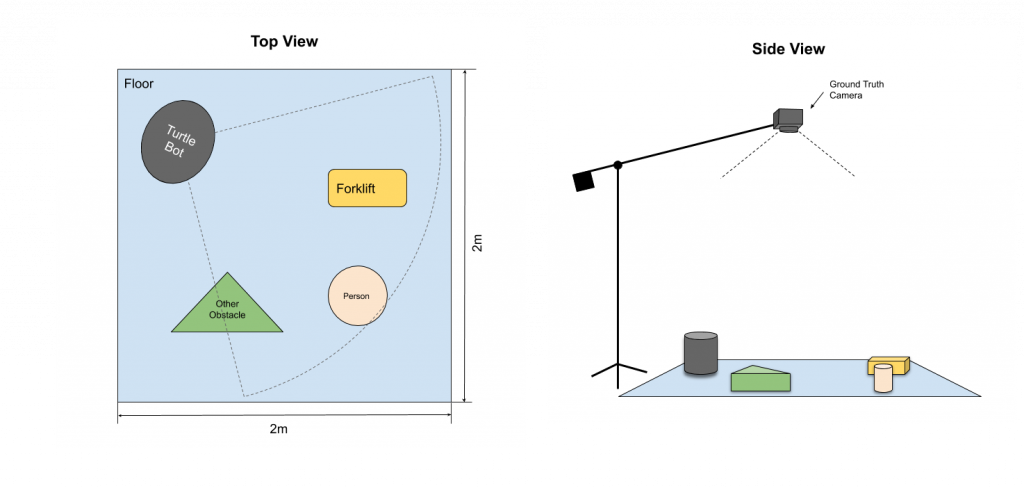
Figure 1: Illustration of ground truth subsystem
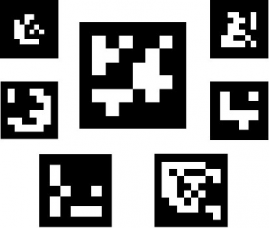
Figure 2: Example barcode/ArUco markers
Alternatives: Besides using an overhead camera, the ground truth positions of objects can also be measured manually, such as by using pre-drawn markers/grids on the ground. However, this will limit the testing and validation scenarios of the real-life system to be static only, and will increase the time consumption of testing and validation.
Obstacles & Environment
To facilitate testing and validation, the environment and obstacles used in the real-life system will be scaled down compared to an actual factory. The environment will be a 2×2 meter flat area with adequate lighting to simulate an open area in a factory where robots will need to recognize obstacles. The obstacles will be scaled down accordingly (1:8), in the form of pedestrian action figures and forklift toys. When using a scaled-down environment, the team can execute a variety of testing scenarios more efficiently since the smaller objects are easier to handle. In addition, the setup required to gather ground truth in a scaled-down environment is much simpler.
Alternatives: Should the scaled-down environment and obstacles fail to adequately represent a realistic factory environment, the real life system can validate the detection and classification requirements using videos of forklifts and pedestrians. In this scenario the obstacle localization requirements would not be validated.