Functional Architectures
Virtual Robotic System
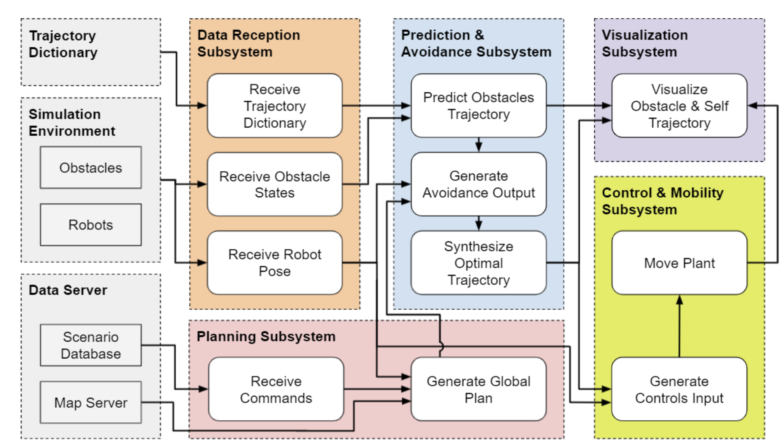
Our virtual robotic system will perform collision avoidance based on the prediction of future trajectories of obstacles. To achieve this goal, we have five major subsystems in the functional architecture for the virtual robotic system: Data Reception, Planning, Prediction & Avoidance, Control & Mobility, and Visualization. All arrows in the architecture represent digital information.
In the Data Reception subsystem, necessary data is received and processed. This includes a pre-built trajectory dictionary which stores past trajectories of obstacles, the current obstacle states, and the current ego-robot pose (i.e., position, heading, and velocity). In the Planning subsystem, waypoint commands and the environment map are used to plan the nominal self-trajectory, without considering dynamic obstacles. In the Prediction & Avoidance subsystem, the system predicts the future trajectories of obstacles using the trajectory dictionary together with the obstacle states acquired in the Data Reception subsystem. Then, it generates evasive maneuvers based on the obstacle predictions and chooses the maneuver it determines to be the most optimal. In the Control & Mobility subsystem, the system controls the robot to execute the chosen evasive maneuver. Finally, in the Trajectory Visualization subsystem the obstacle predictions, robot evasive maneuvers, as well as performance metrics are visualized to validate our requirements.
Real-life Robotic System
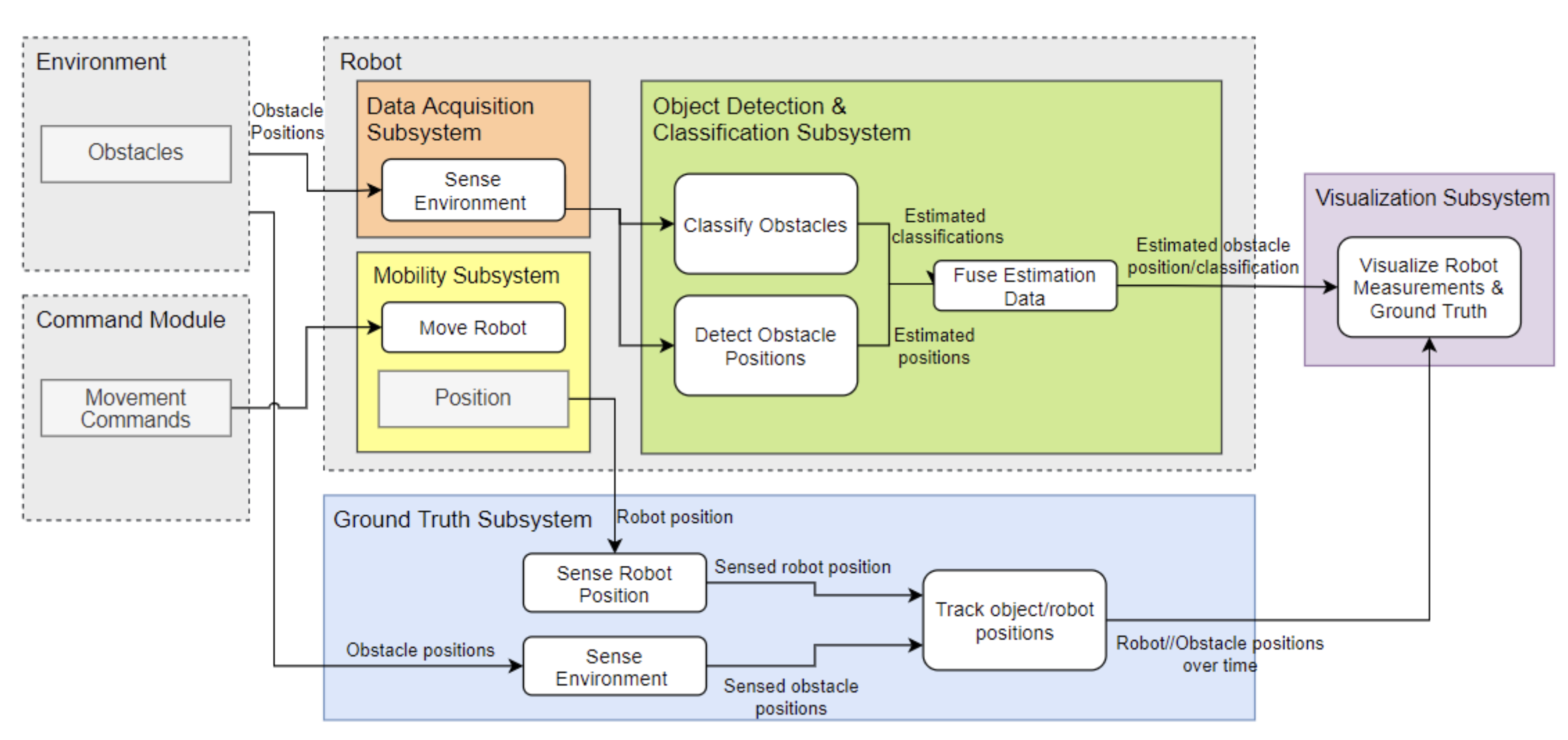
Our real-life robotic system will validate obstacle detection and classification capabilities. It includes five main subsystems: Data Acquisition, Object Detection & Classification, Mobility, Ground Truth, and Visualization. All arrows in the architecture indicate information flow.
In the Mobility subsystem, manual commands are used to actuate the robot. As the robot moves, sensor data from obstacles in the environment are sent from the Data Acquisition subsystem to the Object Detection & Classification subsystem, where the robot estimates the obstacle positions and classifications. The robot’s estimates are then sent to the Visualization subsystem, which compares them against the true values obtained from the Ground Truth subsystem and outputs plots showing the accuracy of the estimations.
Interaction between the Virtual and Real-life Robotic Systems
The real-life system and virtual system are mostly independent and are not tightly integrated. The two systems were split due to COVID-19 limitations on physical testing as well as limited access to full-scale testing facilities and equipment. Consequently, the prediction and avoidance portions of our system pipeline will be validated in simulation. We decided to validate the detection and classification portions of the project in real life because we believe it is valuable to include realistic noise measurements for the sensors, and because this would not require a large-scale environment. Validating perception in simulation would also require maintaining high definition 3D models of obstacles, significantly increasing computational load.
The only connection between the virtual and real-life systems will be the obstacle detection and classification noise characteristics, which will be measured in real-life and then replicated in simulation, so that the simulation results will be more realistic and closer to what they would be if the entire project were conducted in real-life.
Cyberphysical Architectures
Virtual Robotic System
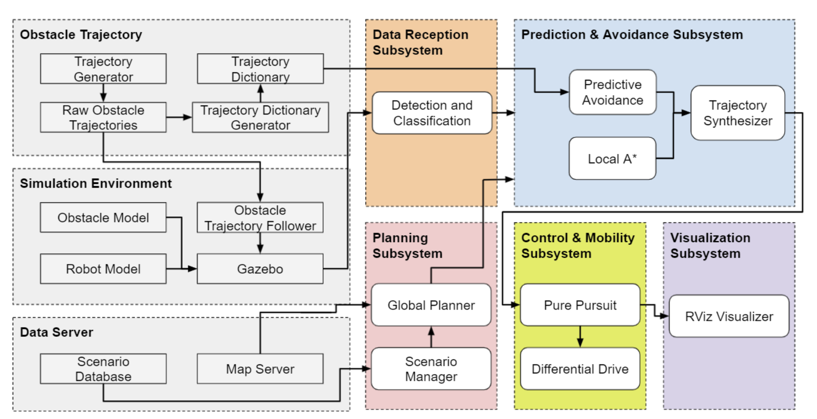
The virtual robotic system’s operation starts from three initial components:
- Obstacle Trajectory: This section includes the generation of the trajectory dictionary. The Trajectory Generator records raw obstacle trajectories from the environment, which are then processed and combined into a single trajectory dictionary that is used later to make predictions.
- Simulation Environment: Our simulation environment used for validation is Gazebo. It will include 3D models for obstacles, the robot, and a factory environment. It will update the states of these models as necessary during the simulation (especially when replaying obstacle trajectories, which is handled by the Obstacle Trajectory Follower block), and will also handle collisions.
- Data Server: This includes a database of the parameters (initial conditions, goal locations, obstacles, etc.) of various collision scenarios, which are used for testing and validation. It also includes the floor map of the simulated environment, which is used later for path planning.
Data from these three components are then fed into the remaining subsystems. First, the floor map along with the given collision scenario’s parameters are used in the Planning subsystem to plan the robot’s global path from its initial location to its goal point. Then, the Data Reception subsystem will continuously receive the states of each simulated entity from the Simulation Environment and apply simulated obstacle detection and classification. The planned path and obstacle information from both these subsystems are then passed to the Prediction & Avoidance subsystem, which either makes obstacle predictions and plans evasive maneuvers accordingly or simply uses the nominal avoidance algorithm: local A*. Afterwards, the chosen trajectory for the robot at each time step is executed using Pure Pursuit with a differential-drive steering system. Finally, the Visualization subsystem uses RViz to display updated model states, predictions, evasive maneuvers, and other relevant metrics.
Real-life Robotic System
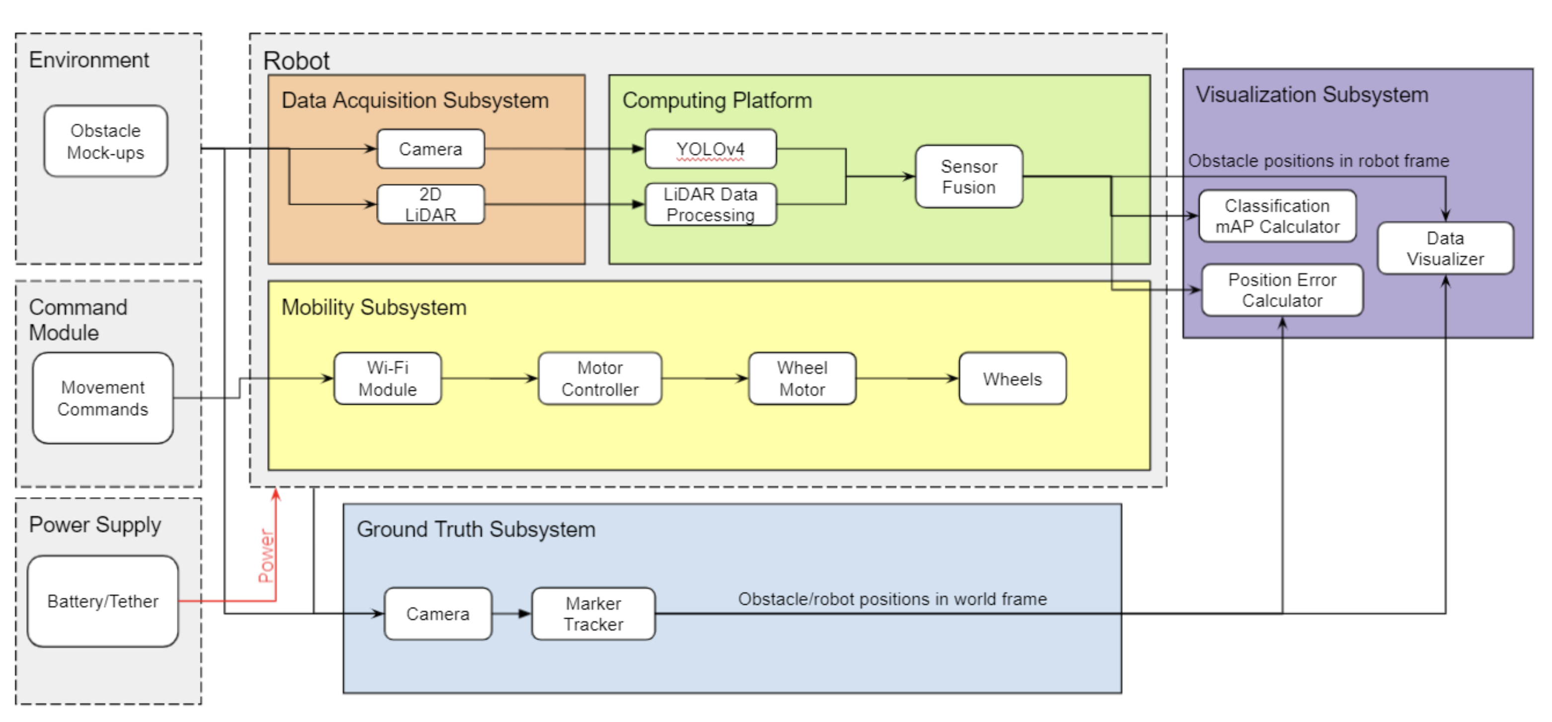
Similar to the virtual robotic system, the real-life robotic system’s cyberphysical architecture has three initial components:
- Environment: This is the testing environment that will be used, which will be a small open area including scale models of realistic industrial obstacles.
- Command Module: This includes the teleoperation commands that will be sent to the robot during operation.
- Power Supply: This can either be a LIPO battery or a tether, and will supply electrical power to the robot during operation.
As in the real-life functional architecture, the robot itself includes three main components. The Data Acquisition subsystem includes the robot’s onboard sensors, which are a 2D LIDAR and a camera. The Computing Platform will process and combine this sensor data, which includes applying the YOLOv4 neural network to the camera images. The Mobility subsystem forms a differential-drive steering system using wheels, wheel motors, and a motor controller board, and includes a Wi-Fi module to allow for untethered operation.
The Ground Truth subsystem will include a separate camera that will track markers (e.g. Aruco) placed on each entity, and will output the positions of these entities in a fixed world frame. The difference between the output from the Ground Truth camera and the output from the robot’s sensors will be visualized in the Visualization subsystem. Performance metrics like position error and mean average precision will also be shown.