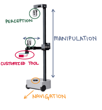
The robotic platform used is The Hello Robot Stretch RE1. The various subsystems – perception, manipulation, navigation, customized tool – work on different parts of the robot as seen in Fig. 1. The perception subsystem makes use of the cameras on the head and wrist. The manipulation subsystem makes use of the lift and arm. The customized tool subsystem makes use of the wrist and tools. The bot comes with a default Stretch Compliant Gripper. This gripper will be replaced was replaced with customized tools that can perform the desired action i.e., pollinating or harvesting. The navigation subsystem makes use of the LiDar and base.
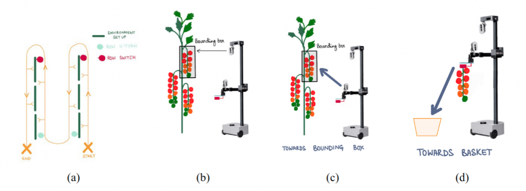
The navigation subsystem enables the bot to traverse the rows of the environment in a path as seen in Fig. 2(a). While the bot is traversing the environment, the perception subsystem is detecting and localizing tomato fruit/flower clusters as seen in Fig. 2(b). The bot stops at a cluster location and actuates its lift and arm towards it such that the tool is in its vicinity as seen in Fig. 2(c). The tool is then actuated at this location – the harvester grips and cuts the tomato bunch ; the pollinator vibrates near the flowers. If the task is harvesting, the bot then drops the bunch near the ground as seen in Fig. 2(d). If the task is pollination, the bot retracts its arm.
- Mobile Robot
The team has decided to use the Hello Robot Stretch RE1. The specifications as seen in the documentation are listed in Fig 3.

2. End Effectors & Customized Tools
The Hello Robot Stretch RE1 comes with a default Stretch Compliant Gripper. This gripper will be replaced with a customized tool that can perform the desired action i.e., pollinating or harvesting. The tools will vary according to the mode of operation. The main considerations while designing this tool are M.N.2, M.N.3, D.N.3. The tool will also have to be integrated with feedback sensors.
- Robot Localization
The robot localization subsystem will estimate the pose of the robot in the environment. This will be done by fusing IMU data, encoder data, and visual-inertial odometry using an EKF. The resulting pose estimate must satisfy M.P.1 from the requirements. If the localization accuracy from EKF does not satisfy the requirement then the alternative approach would be to use an indoor positioning system.
- OOI Identification and Localization
The OOI identification subsystem identifies objects of interest (OOI) around the robot. For the pollination task, OOIs are the tomato flowers and for the harvesting task, OOIs are the tomato bunches in the vertical farm environment. This task needs to satisfy M.P.3 and M.P.5 from the requirements. This will be done by a detection model running on the input RGB images from the Intel RealSense camera. The main considerations while choosing the appropriate detection model will be model accuracy (mAP), inference time, and ease of implementation on the robot’s hardware. Depending on the model, the output of this subsystem can be bounding boxes or a segmentation mask of the identified object.
The OOI localization subsystem will estimate the position of the tomato flowers/bunches in the environment. It will take the object detections as input and use the depth image and robot’s pose to find the exact coordinates of the object in the global frame. This task needs to satisfy M.P.4 and M.P.6 from the requirements.
The process flow of OOI identification and localization are summarized in Fig 4.

- Behavior Planner
The behavior planner will identify waypoints (points at which the robot needs to stop and perform the task) based on OOI localization. Following this, if the robot is not at the waypoint, robot navigation is performed via the tracking controller (Section 8.6) so that the robot reaches the waypoint. If the robot is at the waypoint, the end effector is actuated (Section 8.7) to perform the task.
The process flow of the behavior planner is summarized in Fig 5.

- Tracking Controller
The tracking controller controls the robot’s navigation. The robot will navigate along the rows and have the ability to switch rows while satisfying M.P.2. Based on the desired waypoint, the current robot poses, and row information, motor commands will be generated, and the robot will be actuated so as to reach the desired waypoint.
The process flow of the tracking controller is summarized in Fig 6.

- End Effector Actuation
The manipulation subsystem will operate the customized tool to perform the desired action. Based on the localized OOI, the point of interest (POI) will be estimated. POIs are the points at which the tool must interact with the environment. For the pollination task, POIs are the points at which pollination is to be done and for the harvesting task, POIs are the points at which harvesting is to be done. Based on the desired location, the joint trajectories will be generated, and the tool joints will be controlled and actuated so as to perform the task.
The process flow of the end effector actuation is summarized in Fig 7.
