The system’s cyber-physical architecture is constituted of four major blocks: sensing, perception, navigation, and manipulation, as seen in Fig 1.
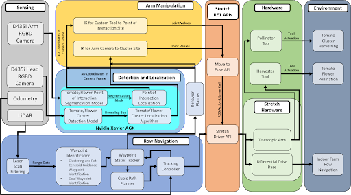
The sense block consists of the sensors used by the robot. These include the RGBD camera, the IMU, and the LIDAR that are on the existing sensor suite of the Hello Robot Stretch RE1.
- Visual sensing – The environment sensed using the RGBD camera.
- Pose sensing – Pose or the robot’s state sensed through IMU/encoders
- Range sensing – The environment sensed using the LIDAR
The perception, navigation, and manipulation blocks show the software components corresponding to the major functions in the functional architecture.
In the perception block, the functions that were previously identified in the functional architecture are elaborated upon –
- To localize the robot in the vertical farm environment
Given the IMU and encoder data, the robot post(x, y, z, roll, pitch, yaw) will be estimated. - To identify and localize the objects of interest
(tomato bunches to be harvested or tomato flowers to be pollinated)
Given the RGB image, an ML model will be applied to detect the OOIs. The subsequent bounding boxes will be processed along with the depth image to extract position of the OOIs with respect to the global frame. - To detect the rows of the vertical farm
Rows will be detected by fitting lines through the LIDAR point cloud.
In the navigation block, the functions that were previously identified in the functional architecture are elaborated upon –
- To deduce the exact waypoints between the rows at which the robot needs to stop
- To plan the behavior of the robot according to the robot pose and desired waypoint
The behavior planner’s job is to switch between the navigation and manipulation tasks. After it receives a list of waypoints from the waypoint identification block, it deduces the desired waypoint. If the robot is not at the desired waypoint, the robot must navigate to it. The behavior planner sends the desired waypoint to the tracking controller. If the robot is at the desired waypoint, the behavior planner switches to the manipulation tasks. - To track the robot to the desired waypoint
The tracking controller’s job is to take in the current position of the robot and the detected rows and calculate velocity corrections in order to keep the robot navigating between the rows at a constant lateral distance. - To actuate the robot base
The velocities from the tracking controller are then converted into wheel RPM and fed into the individual motor controllers for actuating the robot’s base. - To update the waypoints as the robot navigates between the rows
In the manipulation block, the functions that were previously identified in the functional architecture are elaborated upon –
- To deduce the point of interaction or POI
- To generate a motion plan for the end effector to reach the POI
The inverse kinematics planner generates joint trajectories for the manipulator to reach the POI. - To actuate the tool and perform the task
The generated joint trajectories are fed to the joint controller which monitors the feedback from the tool to determine the exact location of the POI. Upon successful actuation of the tool, it will signal back to the behavior planner which then repeats the loop by sending the next waypoint.