The Navigation subsystem’s activities were broken down into several steps spread over the spring semester. The development began with the Hello Stretch RE1 platform familiarization followed by the first Navigation SVD test aimed at measuring odometry accuracy. The University of Michigan Benchmark test was used to evaluate the accuracy of the onboard odometry system. This information will be used in the future to improve navigation accuracy in-case the robot performs below par in the on field tests.
February Progress Update
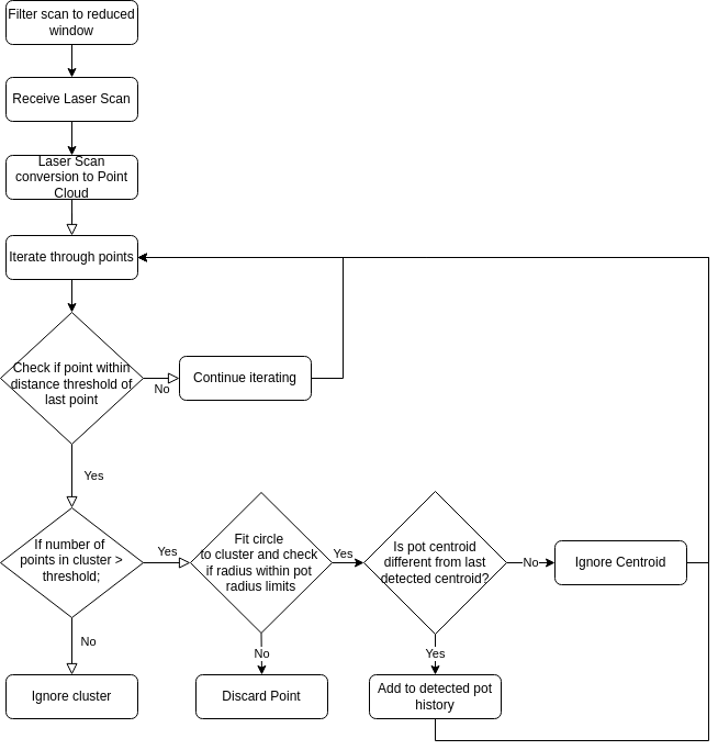
The problem of navigation in a greenhouse environment has both its challenges as well as its advantages. The benefits come from the inherent structure of the environment that can be exploited to make the problem more tractable. The difficulties arise in part due to the sparsity of the LiDAR data which we plan to use for navigation and satisfactory end-of-row detection. For the spring semester, we intend to make a basic reactive navigation system that can detect plant rows, track a path parallel to the rows and stop at the requested way-points. The figure below shows a basic outline of the algorithm that has been drawn up.
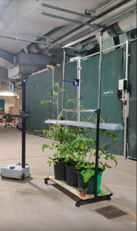
In order to proceed with development of the algorithm, test data had to be gathered. The test setup described in the “Test Environment” page was wheeled out into the main basement area of the NSH building to simulate farm rows. ROS bags were then used to record LiDAR data while tele-operating the robot through the rows. Fig 2. shows the data recording in progress.

March Progress Update
The LiDAR pot detection algorithm is shown in Fig. 3. In a nutshell, the algorithm iterates through the point cloud, clusters points that are close to each other and fits circles to them. The fitted centroid and radius of the pot are then checked against expected values to filter out outliers.
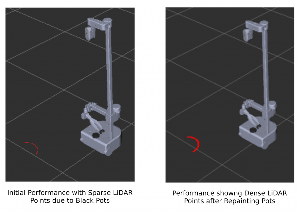
A significant challenge that we initially encountered with the LiDAR identification method was the poor reflectivity of the laser from the black pots that we had. The pots were subsequently spray painted green to better reflect the laser giving a much denser point cloud representation for clustering. Fig 4. shows the LiDAR intensity and density before and after the colour change. The left visualization in Fig 4. shows performance with black pots and the right one shows the performance with green pots.
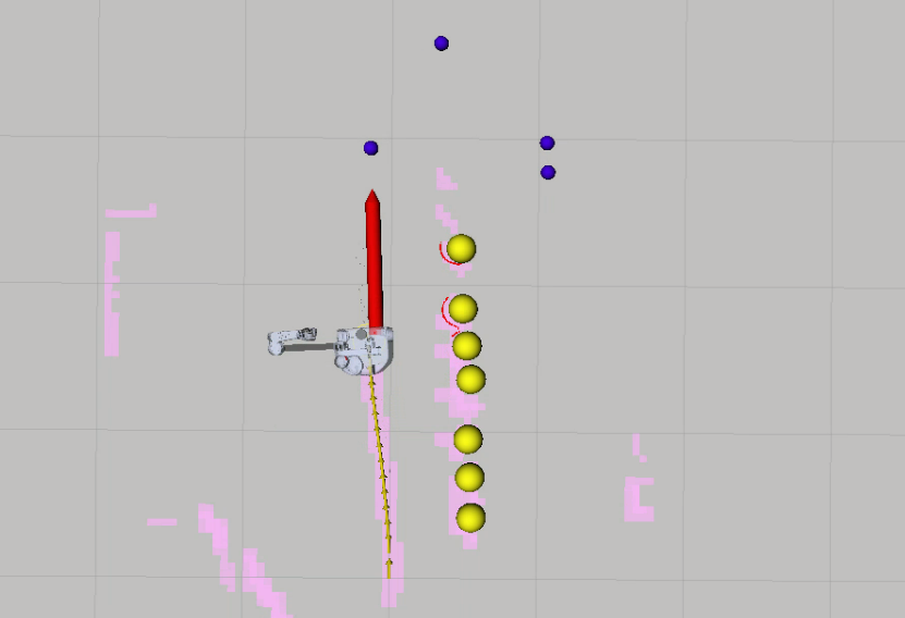
The identified pots were then used to locate intermediate way-points for the robot to track. The tracking was then implemented using a basic go-to-goal controller which was passed target way-points that were parallel to the pots. Finally the row was switched using the Aruco marker to generate turning way-points. The go-to-goal controller in operation is shown in Fig 5.
April Progress Update
Due to problems in implementing our own controller, it was decided to utilize the ROS navigation module that comes with the Hello Robot. The base parameters of the Hello Robot’s local planner was not working well for our purpose. We manually tested the robot in the lab to accurately update the parameters of the local planner. With this change in the navigation module, the updated navigation architecture is shown in Fig 6.
Once the local planner was up and running, the way-point accumulator and publisher was set up. The navigation stack operates in two modes, the explore mode and the exploit mode. In the explore mode, the robot incrementally navigates alongside the rows until a cluster is detected. At this point, the cluster locations are received by the robot and the navigation module is switched to the exploit mode by the high-level planner where it tracks the received cluster location.
The main functions of the way-point accumulator and publisher are to receive the guide-vectors(parallel to the pots) from the LiDAR pot detection module and the inputs from the Aruco markers to create intermediate way-points. These way-points are generated in the moving base_link since it simplifies computations for a reactive navigation application. Except for the row-switch and u-turn segments, all explore and exploit way-points are projected onto the vector parallel to the pots. Fig. 7 makes this process clear.
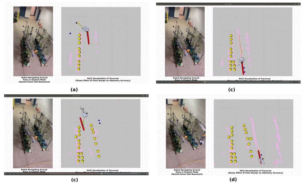
Currently the explore mode has been implemented and tested in our small lab based vertical farm setup. Fig 8. shows the performance of the robot around the two-row farm environment. Fig 9. Shows a collection of side by side images of the physical test performance and the visualization.
Spring Progress Conclusion
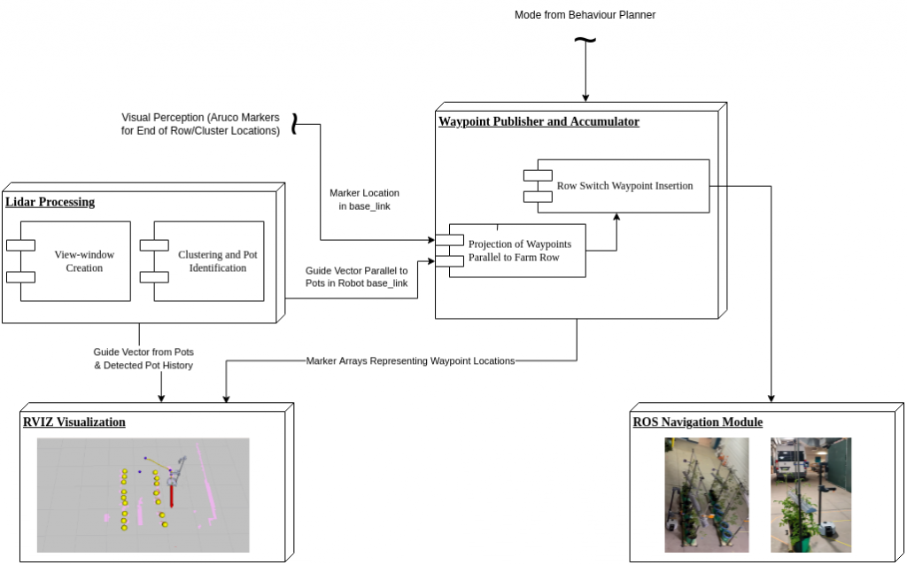
Over the closing weeks of April, the navigation sub-system was integrated with the other sub-systems. Fig 10. shows the updated description of the navigation system with the inputs from perception added to the system diagram.
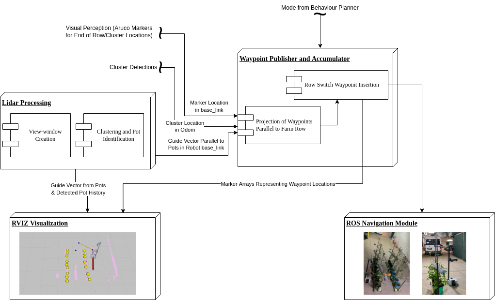
Overall, the navigation system works as expected. Since it is a reactive system, even though the odometry has significant drift, it still performs the necessary tasks. For the fall semester we would like to improve the odometry estimation and implement an improved planner for the row turns. In addition to this we intend to test some additional changes to the local controller in order to make the motions smooth.