Since we are developing our software on an existing robotic platform, the main elements that require CAD are parts for the customized tool for the harvesting and pollination, aruco marker holders and other miscellaneous items for the test environment. Fig. 1 shows the first iteration of the tool design. The inspiration for this design was to utilize a single motor to actuate both the cutter and the gripper to harvest. The sequential actuation of the cutter and gripper was to be implemented using mechanical elements in the tool itself. The design involved a differential gearbox that would divide torque between the two end-effectors of the gripper based on perceived load at the tool faces. The core components of the gear-box were printed and tested; however, the 3D printed gears would not stay in mesh due to radial loads. This design was then discarded in favor of a dual motor system when it was understood that the motors could be daisy chained to simplify the control. Fig. 2 shows the test set-up for the gear assembly.
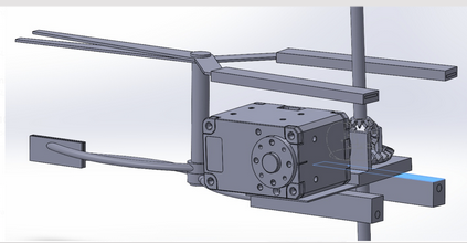
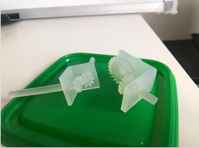
Fig. 3 shows the CAD model for the second design of the integrated cutter and gripper.
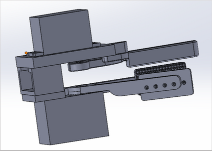
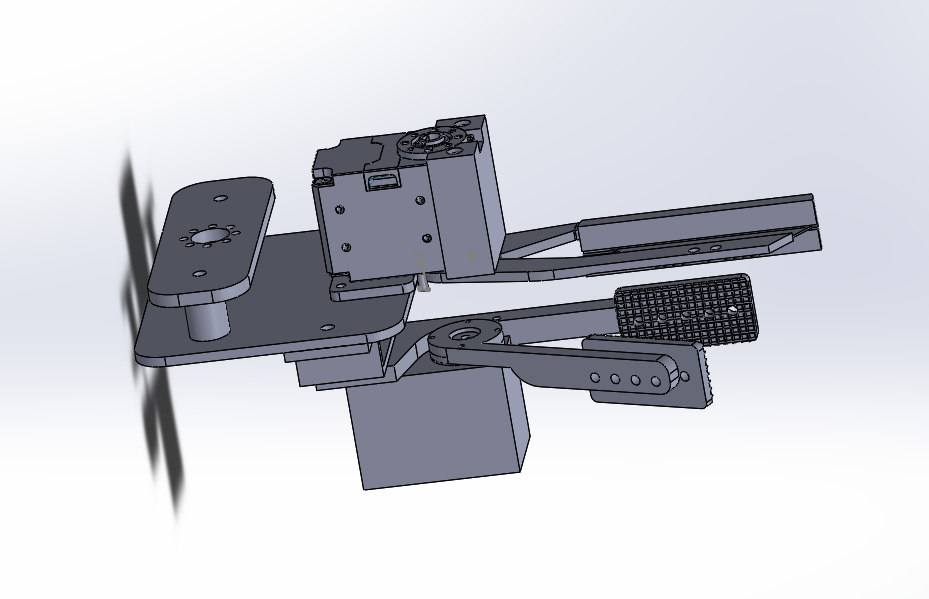
Fig. 4 shows the CAD model for the final version of the harvester tool. It consists of the gripper and the cutter and a connection joint. Two dynamixel XL431 motors power the tool. Fig. 5 shows the CAD model for the pollinator mount. It has the same attachment point as the harvester tool.
The models were 3D printed using PLA and then mounted on the robot. Next steps (FVD goals) for the CAD design include making the tool mounts more compact with easy points of attachment to the robot.