
The sensing and perception subsystem’s main objective is to collect data to aid in localization, navigation, spot detection, and obstacle avoidance. The generation of the environment map is also a key aspect of the project, which the system will accomplish through Asus Xtion.
Sensing Hardware
Function: Spot Detection, Odometry, Obstacle Avoidance
We will use an Asus Xtion depth camera to acquire images and generate point clouds. The device features an “RGB camera, depth sensor and multi-array microphone running proprietary software”, which provide full-body 3D motion capture, facial recognition, and voice recognition capabilities. The depth sensor consists of an infrared laser projector combined with a monochrome CMOS sensor, which captures video data in 3D under any ambient light conditions. The sensing range of the depth sensor is adjustable, and Xtion software is capable of automatically calibrating the sensor based on the physical environment.
The camera will primarily be used to detect the spot in which a platform will park. By combining the data from ultrasonic sensors and vision system, the exact location of the obstacle can be calculated. This will augment the path planning algorithm’s obstacle avoidance capability.
Vision-based odometry using monocular or stereo vision cameras will help in localization and avoiding other moving vehicles in the lot. The data from encoders when coupled with visual feedback from the sensors will help in generating a reliable estimate of the robot’s position.
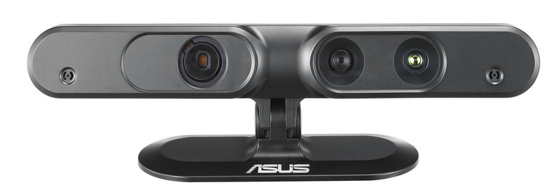
Asus Xtion depth camera
Obstacle Detection using Asus Xtion
The obstacles are defined to be cylinders of 10-50 cm height and 10-120 cm diameter. Our algorithm uses plane fitting of a cylinder model and RANSAC for outlier rejection to segment out cylindrical objects from the point cloud. To increase the performance of the system, the incoming data from Xtion is down-sampled using a voxel grid-based approach. Further filtering is done to retain only a region of interest for the purposes of obstacle detection and crop out everything else. This data is then passed through VoxelGrid and PassThrough filters so that the foreground objects can clearly be differentiated from background objects, such as walls. The objective of this node is to publish the detection of an obstacle on an emergency topic.
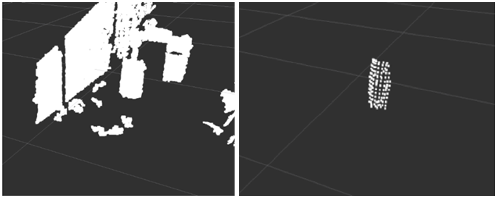
a) Raw Data b) Segmented Cylinder
Obstacle Detection using Laser Range Finder
The LRF module consists of a laser, a CMOS camera and an onboard processor. The module works by emitting a beam of laser which is detected by the camera. The exact depth of the point is estimated by triangulation. When we sweep the laser incrementally between two angles, we would be detecting obstacles that would be half a meter in front of our platform. The subsystem uses a dedicated ROS node which parses and checks the reading from the sensor and declares emergency appropriately.
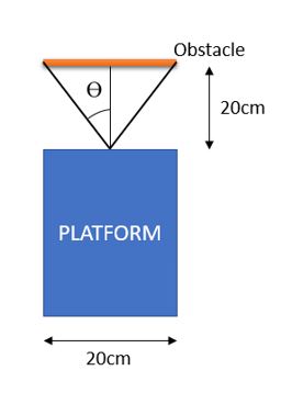
Diagram depicting servo-LRF sweeping
The above figure depicts the calculations related to the rotation angle of the LRF. This shows that the servo needs to sweep an area of +/- 35 degrees from the center of the platform. To do this, mounts were created to attach the LRF to the servo.
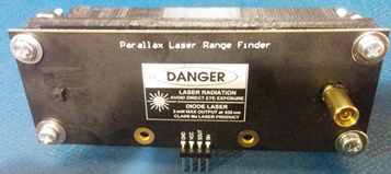
LRF with 3D Printed Mounts
Obstacle Detection using IR
A dedicated proximity detection subsystem is used to prevent collisions with close-range obstacles. The system is implemented in the form of a plug-and-play PCB with sensors and a microcontroller to interpret the readings of the sensors. The system is designed to detect obstacles that are within 50 cm of the platform and cannot be detected using point-cloud data from the Xtion. Any obstacle less than 20 cm causes an emergency to be declared in the system, making the locomotion come to a complete halt. Three IR sensors are mounted on the front of the platform. A dedicated Printed Circuit Board (PCB) was also designed to integrate the IR sensors within the system. The PCB houses an Arduino Nano, voltage regulation unit, and connectors for a power supply and three IR sensors. Open headers are present on the PCB for debugging and the addition of new peripherals.
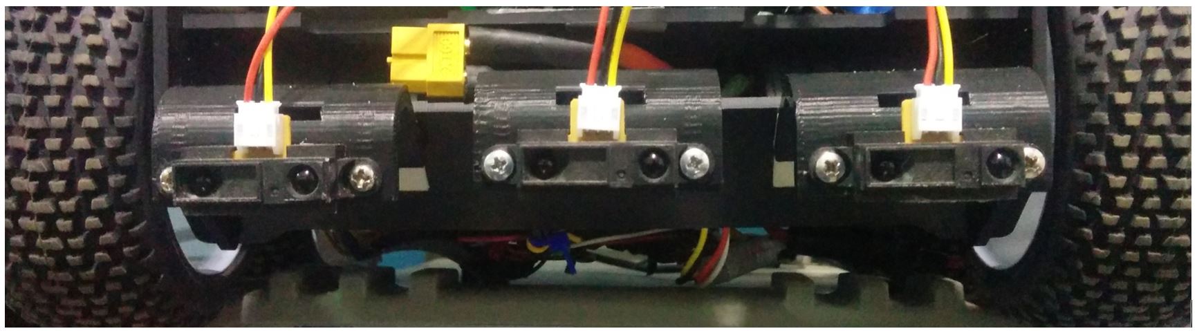
Mounted IR Sensors
The Arduino operates as a ROS node and interfaces with the IR sensors to publish time-stamped range data on a ROS topic. This involves polling the three IR sensors and publishing the range data if the range is less than 50 cm. A separate “emergency” ROS node running on the SBC interprets range data and publishes the current state of the emergency. Figure 40 depicts the time-stamped range data being published on the left terminal window and the corresponding emergency state on the right. An emergency state of “0” indicates that no emergency has been detected and the system can continue normal operation. When a “1” is published on the “emergencyState” topic, the system is in a state of emergency and needs to stop immediately.
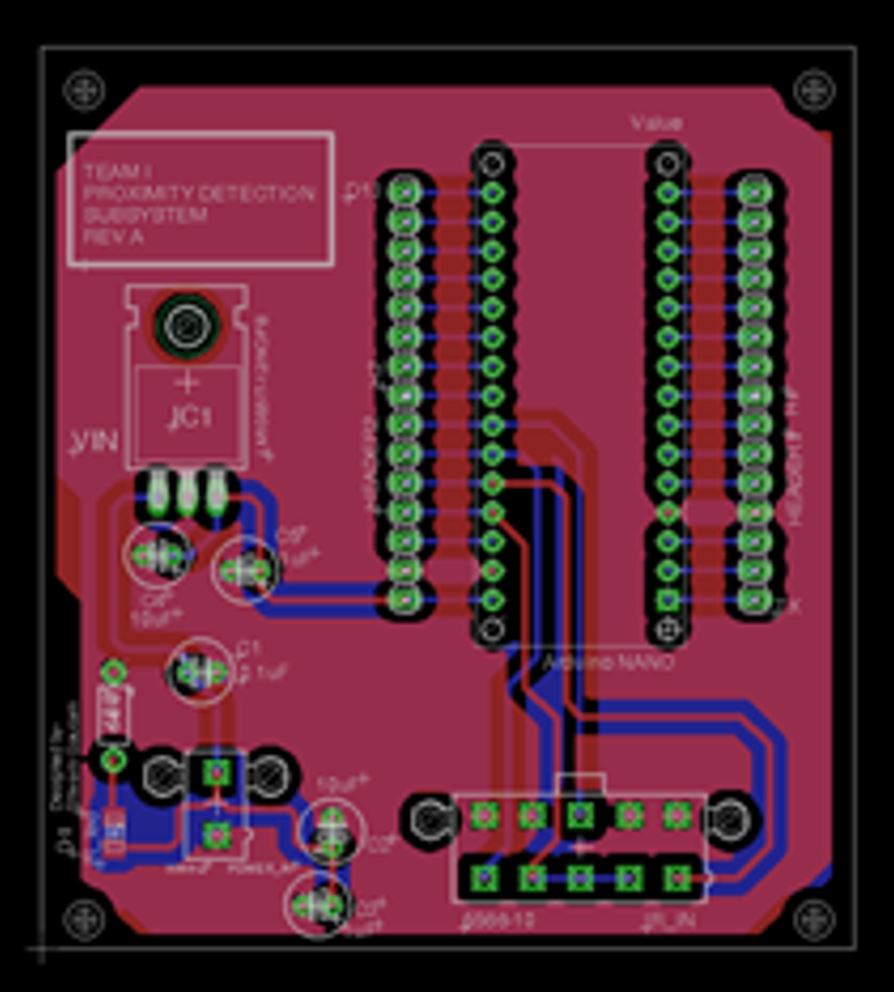
PCB Design- Rev 1
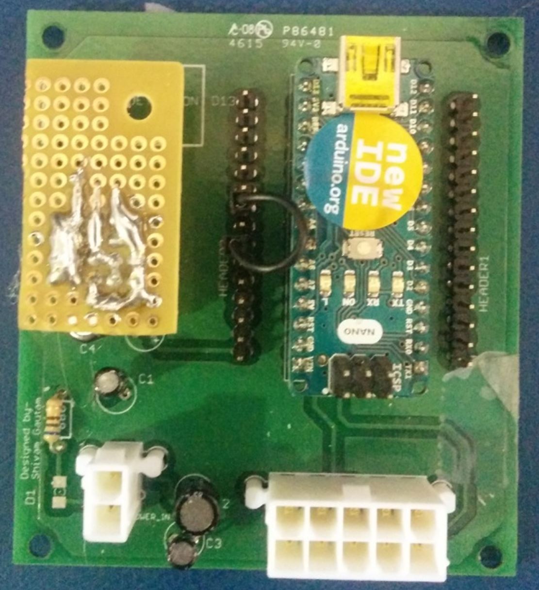
Manufactured PCB 1
The first revision of the PCB performed really well and also served as a source to power additional components like USB hubs.Additional components, like the USB hub, had not been taken into account during the design of the first iteration of the PCB as it was assumed that they would be powered by either USB or through Oculus Prime’s power distribution board. Further shortcomings of the board included not having LEDs for diagnostics and dedicated fuses for lines powering the USB hubs. In addition to this, the PCB lacked additional connectors for powering other devices.
To mitigate this problem, a second revision of the PCB was designed to include-
- A dedicated connector for the USB hub
- A dedicated fusing for the line powering the USB Hub
- LEDs for diagnosing power for board and subcomponents.
- Additional connectors for power components that might be added to the platform.
- Changing Voltage Regulator from LM7805 to LM1084 (Higher current rating -5A)
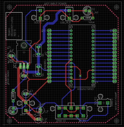
Redesigned PCB Layout