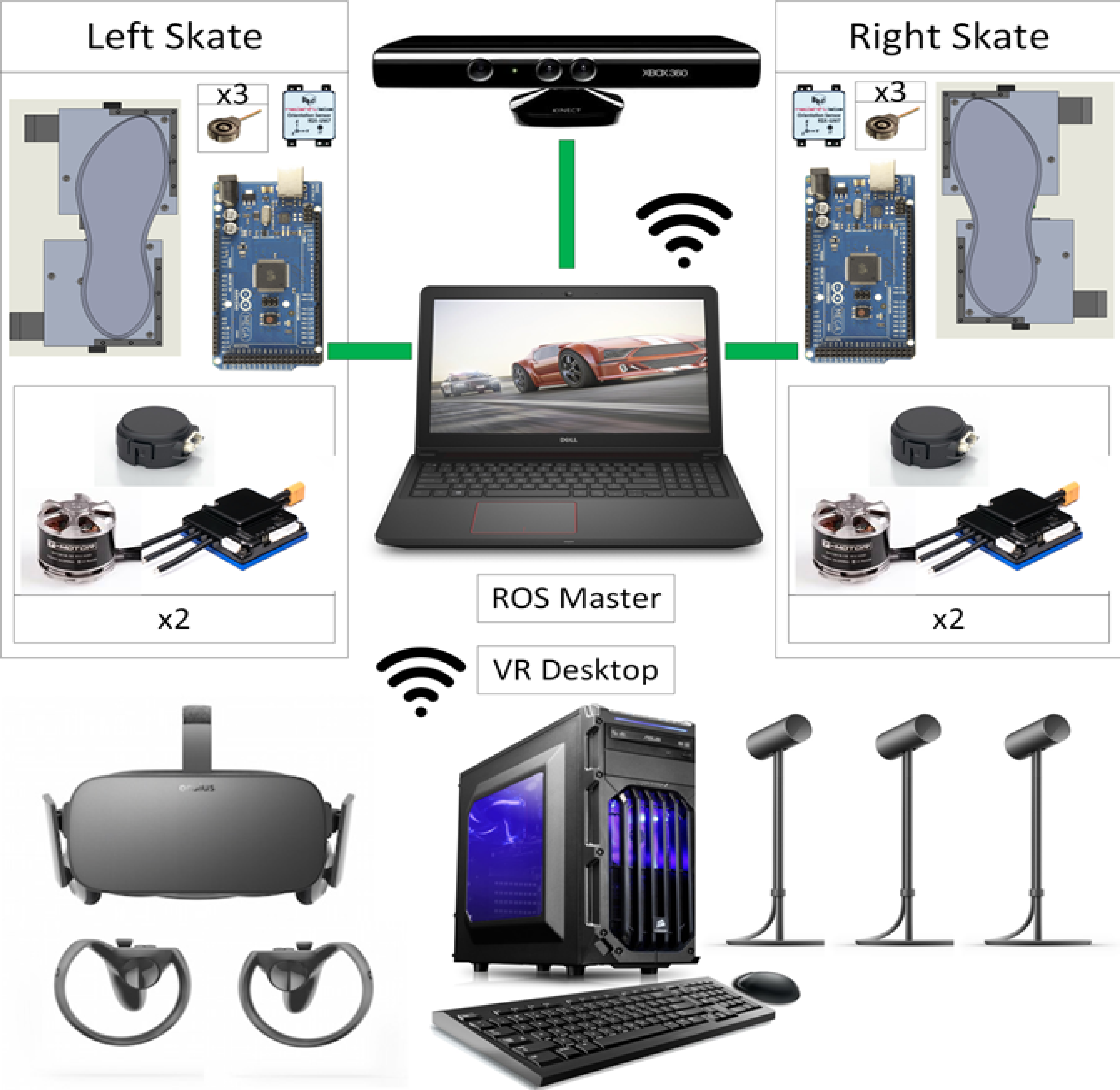
Figure 1: Current system architecture
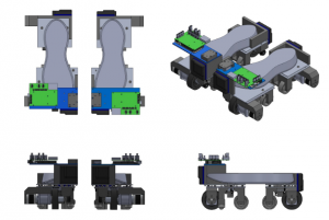
Figure 2: Skates
The current system architecture is demonstrated in Figure 1. It comprises of a ROS master which is the higher level controller, a Desktop PC which is a VR renderer, powered skates that have a lower level controller, Kinect for room scale perception and Oculus Rift to display the VR world.
As depicted in the cyber-physical architecture, the system is comprised of 3 subsystems –
Powered skates
Figure 2 represents the latest concept of our skates. Depicted in the picture are the top, front, side, and isometric views of the powered skates, with the user’s shoes placed on them. Each skate comprises of two halves, each one almost entirely independent of the other. This enables the system to preserve the natural vertical degree of freedom between the toes and the heel of the user, allowing for a more natural gait. This also allows the system to easily accommodate all shoe sizes between US sizes 7 to 14. Each half-skate is powered by a dedicated 400W motor and drivetrain.
Most of the PCB design was retained for the Spring Validation Experiment as well, with some changes to correct the force-sensing circuit. A few minor changes and additions were made to improve overall functionality and for ease of cable routing, as well as an additional safety feature in the form of a dead man’s switch. We shifted the board from under the skates to over the user’s toe-box in order to provide more ground clearance as a risk mitigation strategy. The mechanical design improvements included wire strain relief, passive wheels in lieu of casters, and dedicated calibration rigs.
Sensing and control
a) On-board Sensing:
The envisioned primary purpose of this subsystem is to bridge the gap in tracking the state of feet, between sensing the user’s intent at toe-off and sensing the foot velocity when approaching heel-strike. The objective is to match the user’s foot velocity and position, so there would be relatively less error between the two if they are both measured by a common system.
Force sensors & IMU:
We plan on implementing this function by embedding a force plate on the surface of each platform and use the data acquired in terms of normal and shear forces to calibrate our system to predict the user’s intent within an acceptable range of error. Force sensors are a standard to detect the gait of the user. We have 3 force sensors on each skate to give us the resolution we need.
http://Reference: http://jap.physiology.org/content/89/5/1991
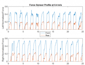 Figure 5: Force profile of a user using our sensors
Force sensors are located at the ball and heel of each foot and played a large role in the Spring semester. Robust and calibrated force sensor output for a user can be seen in Figure 5.
b) Room positioned sensing:
The perception system uses computer vision techniques on data acquired from a Kinect to estimate the user’s Centre of mass/waist location and pose in real-time, and along with the data of the user’s current foot position, helps the planning system in determining the magnitude and direction of movement of the motorized skates, so that the user stays centered within the control volume.
Figure 6 Shows the user’s on the skates being tracked by the Kinect’s openni tracker package.
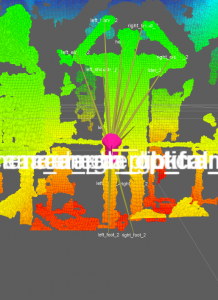
Figure 6: Skeletal tracking
c) Controls:
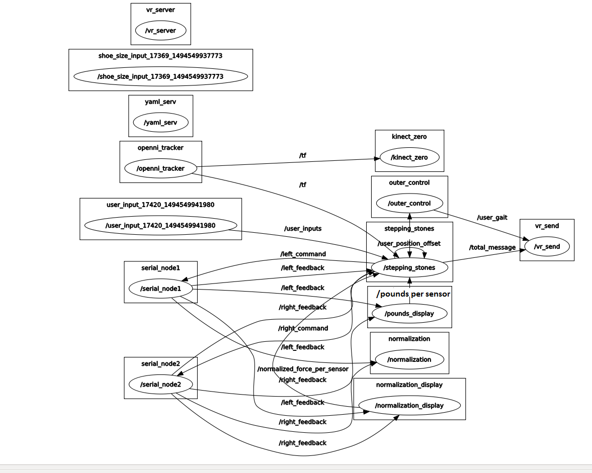
Figure 7: Software Architecture
The higher level controller is designed over ROS. Refer Figure 7 to see all the software nodes that control the skates. Arduino, Windows are treated as serial nodes. Stepping stones is the aggregator node that combines most of the sensor information and sends out the command to the left and right skates. Outer-control node is the one that calculates the user gait.
The plan is to interface all the selected sensors with ROS and collect data for making decisions. This means we are going with a one computation platform approach. This decision was made solely keeping in mind the synchronization & visualization of data and also relative positions between the feet/bots in real time.
The planning and control system has the additional task of combining the data from the onboard and the user-attached sensing systems with that from the perception system to come up with a control strategy for the motors so that it successfully centers the user and maintains balance in every stride the user takes.
The first step to try controls is in a simulation. A simulation environment will provide a great platform to have trials using different force profiles on the skates on which a simulation of a walking human is on.
Non-locomotion virtual reality interaction platform
We used the Oculus Rift to demonstrate our VR integration. It is already equipped with two hand controllers, three room scale sensors, and an X-box controller.
Figure 7 shows a user donning the Oculus Rift, comprising of a VR headset and a pair of hand-controllers
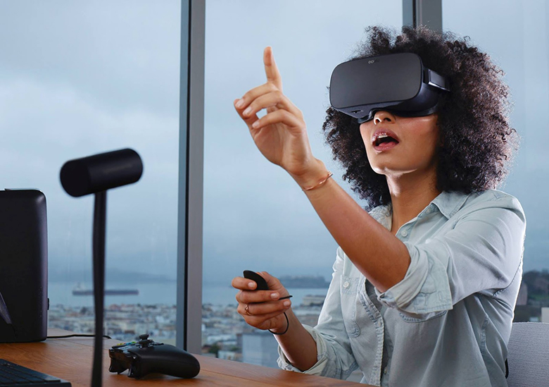
Figure 8: The Oculus Rift gear (Source)
Further details and specifics can be found in the ‘Implementations’ tab.