List of Tests
1. Bench-top tests
All tests under this category will involve placing the skates on the bench and observing its behaviour and characteristics for various inputs and conditions.
1.1. Kinect-based velocity control
Objective: To demonstrate modulation of skate velocity based on user distance from starting position.
Elements: Kinect user tracking, Steady-state position error controller
Equipment: Power and communication cabling, ground position markers
Procedure:
- Mark ground locations at 2m, 3m, and 4m from the Kinect.
- Connect the power supply to the skate, and connect the Kinect and skate to the laptop.
- Run ROS launch file and starts rosbag recording.
- Direct user to stand ~3m from Kinect in calibration pose.
- Enter a 0.2 m/s velocity target on laptop, wait 5 seconds for velocity to stabilize.
- Direct user to walk forward 1m, waits 5 seconds for velocity to stabilize.
- Direct user to walk backward 2m, waits 5 seconds for velocity to stabilize.
- Direct user to walk forward 1m, waits 5 seconds for velocity to stabilize.
- Enter 0 m/s velocity target on the laptop.
Verification criteria:
- rosbag data shows calculated encoder velocity of 0.2m/s +/- 10% at (5) and (8).
- rosbag data shows calculated encoder velocity of 0.25m/s +/- 10% at (6).
- rosbag data shows calculated encoder velocity of 0.15m/s +/- 10% at (7).
1.2. Force sensor circuit
Objective: To achieve full calibration of the force sensor.
Elements: Force sensing Equipment: Torque wrench, standard weights
Procedure:
- Pre-load the force sensors appropriately by tightening the bolts of the top plate using a torque wrench.
- Connect the Arduino to the laptop.
- Start the ROS node on the laptop.
- Load the force sensors with standard weights and calibrate the sensors for its full range.
- Repeat for each force sensor.
- Direct user to stand on both skates, and record the force values.
- Direct user to stand on each skate, one at a time. Record the force values.
Verification criteria: The sum of force values recorded in step 6 is a good indication of the user’s weight, with an error bound of 10kg. The sum of force values on each skate recorded in step 7 is also accurate to within the same error bound.
1.3. PCB changeover
Objective: To verify that the new PCBs does not have connection issues, is being powered correctly, and performs all functions satisfactorily.
Elements: PCB
Procedure:
- Complete all connections between the PCBs and the various sensors, actuators, microcontroller, and power supply on both skates.
- Connect the microcontroller to the laptop, and switch the power supply on.
- Load the force sensors arbitrarily and record the readings.
- Swing the skates around arbitrarily and record the IMU readings.
- Specify arbitrary motor velocity values on ROS, and observe the motors.
- Load the motors arbitrarily by friction and observe the speed and current draw.
- Record the encoder readings.
Verification criteria: Readings from the force sensors, IMUs, and encoders are sensible. The ESCs are able to source enough current to maintain motor speed under loaded conditions.
1.4. Quick direction reversal
Objective: To demonstrate that the new electronic speed controllers support trip protection requirements.
Elements: Electronic speed controllers (ESC), PCB to ESC interfaces
Procedure:
- Connect the power supply to the skate, and connect the skate to the laptop.
- Load serial_motor_commander Arduino test code onto the skate.
- Start serial message logging.
- Command 30% forward speed with ramp and wait 5 seconds.
- Command 30% reverse speed with rapid ramp and wait 5 seconds.
- Command 0% with ramp and stop serial message logging.
- Start new serial message logging.
- Command 30% reverse speed with ramp and wait 5 seconds.
- Command 30% forward speed with rapid ramp and wait 5 seconds.
- Command 0% with ramp and stop serial message logging.
Verification criteria:
- Measured encoder velocity achieves forward limit to reverse limit within 100ms.
- Measured encoder velocity achieves reverse limit to forward limit within 100ms.
2. User tests
This family of tests involves a user wearing the skates and performing some kind of motion, and is aimed at demonstrating a specific capability. The logistics for this class of tests has been listed in Section 2 of this document.
2.1. Force sensor robustness
Objective: To ensure that the wire connections from the force sensors are satisfactorily robust.
Elements: Physical skates
Procedure:
- Strap the skates securely to the user’s feet.
- Direct the user to walk around for 15 seconds (with the skates powered off).
- Connect the Arduino to the laptop, and read the force sensors.
- Repeat with two different users, with varying shoe sizes.
Verification criteria: After each user finishes walking, the force sensors show sensible readings when connected to the laptop.
2.2. Kinect-based velocity control
Objective: To demonstrate low-rate user centering sufficient for force-based control steady-state error.
Elements: Kinect user tracking, Steady-state position error controller
Equipment: Power and communication cabling, ground position markers
Procedure:
- Mark ground locations at 2m and 3m from the Kinect.
- Connect the power supply to both skates, and connect the Kinect and skates to the laptop.
- Strap the skates securely to the user’s feet.
- Run the ROS launch file.
- Direct the user to 2m from the Kinect in the calibration pose.
- Enter a 0.2 m/s velocity target on laptop, direct the user to begins walking.
- Direct the user to walk for 20 seconds to train for constant velocity walking at the 2m position.
- Command a fade of the starting position from 2m to 3m from the Kinect.
- Direct the user to continue walking at a constant velocity until reaching the 3m position.
- Direct the user to continue walking at a constant velocity for 10 seconds.
- Command a fade of the starting position from 3m to 2m from the Kinect.
- Direct the user to continue walking at a constant velocity until reaching the 2m position.
- Direct the user to continue walking at a constant velocity for 10 seconds.
- Enter 0 m/s velocity target on the laptop.
Verification criteria:
- The user is re-centered in steps (10) and (13) in less than 30 seconds.
- The user does not overshoot the positions in steps (11) and (14) by more than 0.25m.
2.3. Offline force control
Objective: To demonstrate valid identification of walking velocity and stances phases.
Elements: Force sensor calibration, walking velocity estimation, stance phase state machine
Location: Wean Hall 1324
Equipment: Camcorder and tripod, instrumented split-belt treadmill, motion capture system
Procedure:
- Setup treadmill per lab instructions.
- Calibrate motion capture system per lab instructions.
- Setup camcorder on tripod to capture tester on treadmill.
- Connect the power supply to both skates, and connect the skates to the laptop.
- Attach a waist location marker on the user, and secure the skates to the user’s feet.
- Run the ROS launch file.
- Before each test, start a rosbag recording and the camcorder recording, and direct the user to perform a heel strike to synchronize the data sets.
- Direct the user to lean to forward limits, lean to backward limits, and return to neutral.
- Direct the user to pick up a foot, lean to forward limits, take a single step.
- Direct the user to take two natural, continuous steps.
- Repeat steps (7) – (9) three times.
- Set a 0.2m/s treadmill velocity.
- Direct the user to walk continuously for 20 seconds.
- Set a stationary treadmill velocity.
- Repeat steps (11) – (13) twice each for 0.2m/s, 0.35m/s, and 0.5m/s.
- Perform lab equipment shutdown and clean up.
- Process treadmill and motion capture data.
Verification criteria:
- Classification of single stance and double stance in ROS corresponds to automatic labeling using treadmill data and manual labeling using camcorder video.
- Classification of in place and in motion in ROS corresponds to automatic labeling using treadmill data and manual labeling using camcorder video.
- Walking velocity estimates in steps (9) – (15) correspond to measured velocities given treadmill target speed and motion capture position by +/- 10%.
2.4. Adaptive control
Objective: To validate the state diagram and test the control logic using outputs from sensors deployed currently viz. the Kinect, force sensors, and the IMU.
Elements: Kinect user tracking, steady-state position error controller, walking velocity estimation, stance phase state machine
Procedure:
- Strap the skates securely to the user’s feet.
- Launch the ROS Master.
- Direct the user to transition from stance to a step, and then to walking for 15 seconds.
- Direct the user to come to a halt.
Verification criteria: The user’s mean position in the direction of walking is maintained in the specified time, within an error bound of +/- 1m.
2.5. E-Stop
Objective: To allow the user to bring the system to a halt using a hand-held emergency stop button.
Elements: Physical E-Stop button, low-level Arduino controller, Arduino-ROS interface
Equipment: E-Stop button
Procedure:
- Strap the skates securely to the user’s feet.
- Launch the ROS Master.
- Direct the user to hold down the E-Stop button to start the cycle.
- Allow the user to walk until stable speed is attained.
- Direct the user to release the E-Stop button to stop the cycle.
Verification criteria: The skates ramp up to the target velocity only after the user holds down the E-Stop button, and continues to run only as long as the user is holding down the button. The skates ramp down to a halt when the user releases the button.
2.6. VR and adaptive control
Objective: To achieve the same capabilities as in 4.2.4, while immersing the user in virtual reality and ensuring user comfort.
Elements: Virtual reality integration, user comfort
Procedure:
- Strap the skates securely to the user’s feet.
- Secure the head-mounted display (HMD) to the user.
- Display the virtual reality environment on the VR headset and on a projector.
- Direct the user to transition from stance to a step, and then to walking for 15 seconds.
- Translate the viewpoint in virtual reality as a function of the user’s gait.
- Reflect the translation of the viewpoint in the HMD and on the projector.
Verification criteria: The user is able to walk for the duration specified without feeling any major discomfort. The translation of the viewpoint scales realistically with the user’s walking speed and pattern.
3. VR test
Objective: To display a virtual world and on the head-mounted display (HMD), and translate the viewpoint in the virtual world as a function of user velocity through ROS.
Elements: ROS-VR interface, network interface
Location: The Cage / MRSD Lab (NSH B-level)
Equipment: HMD, PC / laptop (VR), laptop (ROS master) Personnel: 1 team member
Procedure:
- Start the ROS program to establish a network connection between the laptop (ROS master) and the PC / laptop (VR).
- Display the virtual environment in the HMD and on the projector.
- Set user velocity on ROS.
- Observe the change in the viewpoint velocity on the display.
- Change the user velocity to different values, and observe the changes to the viewpoint velocity on the display.
Verification criteria: The viewpoint velocity maps realistically to the input user velocity command.
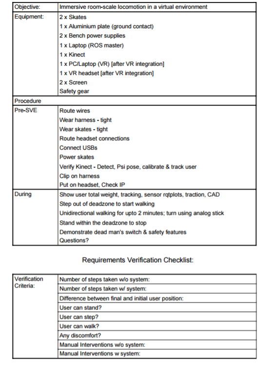
Spring Validation Experiment
Objective: To demonstrate the full capabilities of the powered skates and achieve immersive natural room-scale locomotion in a virtual environment.
Elements: Integrated system
Location: NSH 3002 Equipment: (Same as a routine user test)
Personnel: (Same as a routine user test)
Procedure:
- Direct the user to walk from one end of the room to the other at a normal pace, and measure the number of steps taken.
- Secure the skates to the user’s feet, and the head-mounted display (HMD) to the user’s head. Secure the E-Stop to the user’s body.
- Start the ROS master.
- Display the virtual world in the user’s HMD and on the projector screen.
- Direct the user to start exploring the virtual world at a limit of 0.5 m/s.
- Count the number of steps taken by the user for 2 minutes.
- After 2 minutes, direct the user to stop and end the demo.
Verification criteria:
- The number of steps taken by the user when using the skates is at least 5 times the number of steps taken to walk across the room.
- The user’s final position at the end of the test in the direction of walking is not more than 1m away from the start position.
- The user does not feel any major discomfort due to the VR display.
- The user is able to stand, step, and walk for the duration of the test without losing balance.
Fall Validation Experiment (successfully completed)
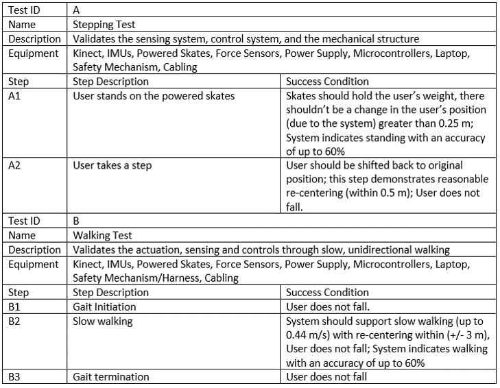
Spring Validation Experiment (successfully completed)