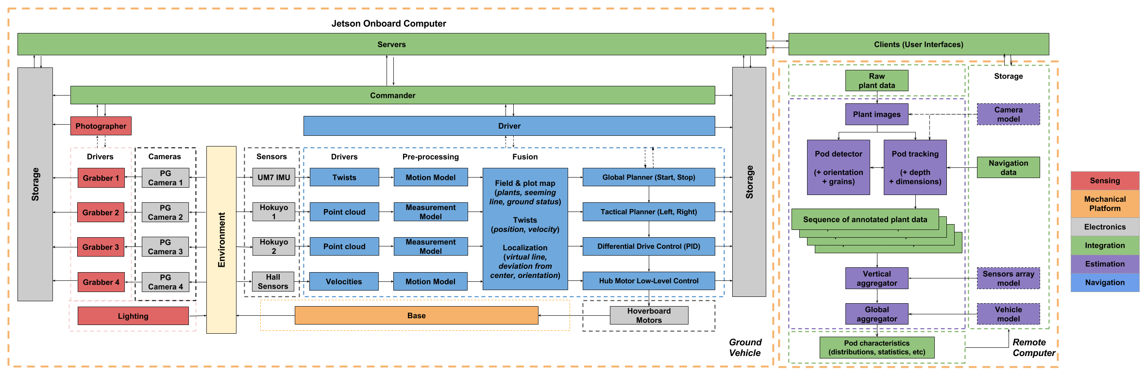
A graphical representation of the Cyber-physical architecture of the system is shown in Figure 1.1 The same coloring scheme as the functional architecture is used.

Figure 1.1 Cyberphysical Architecture for SoyBot
To gather data from the plants, a set of cameras is controlled by the onboard computer. All frames are captured at specific intervals and then synchronized, tagged, and recorded on a local storage device. Similarly, a set of localization sensors comprised of a down-looking camera, a planar lidar, and an IMU are also controlled by the onboard computer. All acquired data is synchronized, tagged, and recorded.
With the latter set of data points, the robot localizes itself with respect to the structured environment of the field. It estimates its motion with the camera and estimates its relative pose with respect to the plants using the lidar range measurements. Merging these pieces of information with the map of the field, the robot adapts its behavior and controls its drive train accordingly. Since the missions only consist of straight lines, motion planning and control are lumped together.
During the whole operation of the mission, power is supplied by a set of batteries whose state is monitored and reported at all times. Similarly, the entire process is configured, monitored, and controlled via two user interfaces: one on the rover and the other on the remote computer. Additionally, a wired connection is required to download the outcome of the mission to ensure speed and reliability.