The following is an outline of the electrical subsystem of Soteria and the power distribution PCB.
The electrical layout of Soteria can be seen in Figure 1. A 48V 20A power supply provides power to two motor controllers, each of which power/control two motors. The 48V is routed routed from the supply to a relay, then to the terminal block where it will be distributed to the 2 motor controllers. The motor controllers are connected to the Jetson (the processor) via RS232 communication protocol.
A 12V 2A power supply provides power to the PCB which is distributed to the Jetson, Arduino, and kill switch. When the kill switch is activated it opens the relay causing power from the 48V power supply to be disconnected from the circuit. This will cut power to the motor controllers and motors, therefore preventing actuation of the exoskeleton. Three IMUs are connected to the Jetson via USB. These IMUs are powered via the Jetson. Lastly an Arduino is powered from the PCB, this is available for add on capability, however in the current design it is not used.

Fig 1: Electrical Schematic of Soteria
The power distribution printed circuit board (PCB) houses the relay and terminal block to distribute the 48V 20A to the motor controllers/motors. It also distributes 12V 2A to the Jetson, Arduino, and kill switch. Figure 2 shows the final board layout and Figure 3 shows the wiring diagram of the board. A diode is used for reverse voltage protection, and a status LED is used to indicate 12V is being provided to the board.
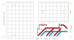
Fig 2: PCB board layout
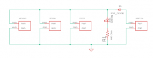
Fig 3: PCB wiring diagram
Data Sheets for all components