SVD Performance Evaluation
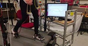
Figure 1: The Sensing System for SVD
(IMU’s roll and pitch shown on the screen)
The Spring Validation Demonstration (SVD) allowed us to compare our system against our requirements. To carry out the demonstration we set up a sensing system by attaching IMUs to the exoskeleton thigh brace on person’s distal femurs, and attaching FSRs to both the toe and heel of each foot, as shown in Figure 1. Table 1 shows the validation demonstrations conducted and the results obtained.
Table 1: Performance Evaluation against SVD
| Subsystem | Requirement Validated | Performance |
| Sensing Subsystem | MR2. Measure user’s pelvic orientation within ±10°; | We inclined the exoskeleton to specified angles of 0, 10, 20 degree using a protractor, and read the orientation output from IMU.
For all trials, the IMU measurements were within 2 degrees of actual orientations. |
| MR3. Determine user’s hip joint angle within ±10°; | We Rotated the joint by hand to specific angles of 0, 10, 20 degrees for both the HAA and HFE using a protractor, and read the orientation output from IMU.
For all trials, the IMU measurements for both HAA and HFE were within 2 degrees of actual orientations. |
|
| Processing Subsystem | MR1. Determine user’s pelvic velocity within ± 0.3 m/s; | We had one teammate walk on the treadmill for 30 seconds and recorded the predicted forward center of mass velocity and compare the mean velocity with the treadmill velocity.
While the treadmill velocity was 0.8 m/s, the calculated mean forward and sideward velocities are 0.7 m/s and -0.09 m/s, respectively. The plots for calculated CoM velocity are shown in Figure 21. |
| MR4a. Classify leg in swing with a recall of 70%
MR4b. Classify leg in swing with a precision of 80% |
We had one teammate walk on the treadmill for another 30 seconds and recorded the predicted and ground-truth values of swing leg detections.
For the left leg, we obtained 98% precision and 93% recall; for the right, we obtained 98% precision and 99% recall. The detected swing leg is plotted together with the ground truth in Figure 22. |


Figure 2: Performance Evaluation of CoM Velocity Calculation

Figure 3: Performance Evaluation of Swing Leg Detection
From Table 1 and Figures 2 and 3, the performance of our system in SVD met our scenario and metrics. Other than those demo shown in SVD, we also had one teammate walk on treadmill with our one-side exoskeleton. While the passive walking, it fitted the person securely as shown in Figure 4.

Figure 4: Secure Fit Test
Table 2: Performance Validation against Test Plans
| Subsystem | Requirement Validated | Performance |
|---|---|---|
| Electrical Subsystem - Motor Reverse Current Dissipation Circuit Test | MN3 | Performance Reqs: Digital output line goes high When the motors are spun by hand (signifies an over voltage is detected) The MOSFET gate is opened. How it performed: Both of these metrics were validated when this test was conducted. The RoboteQ GUI was used to ensure the digital output pin went high and a multimer was used to determine continuity between the gate and the drain of the MOSFET, therefore ensuring the gate had opened. |
| Electrical Subsystem - Power/Emergency Stop test | MN3, MR1-9 | Performance Reqs: Jetson, both motor controllers, USB hub, and IMUs are powered by the 12V supply (Jetson is on and power LEDs are illuminated) Motor Controller power switches power the motor controllers on and off 48V supply provides power to the motors (they respond to actuation) The emergency switch kills power to the motors (they do not respond to actuation), and all other components remain powered. How it performed: Verified all electrical systems were powered on and the motors could be actuated. When the Emergency stop was activated, we used a multimeter to ensure 48V was no longer connected to the motors - that passed. The motors could no longer be actuated as well. But all other electrical components remained powered as required. |
| Mechanical Subsystem - Exoskeleton frame and its weight, balance, and user-fit requirements | MN1, MN2, MN3, MN4 | Performance Reqs: Exoskeleton is built and complete Calculated CoM is no more than 3cm from the user’s CoM Weight of exoskeleton is less than 10kg The exoskeleton does not slip and moves smoothly with user motions User does not feel pain or discomfort while wearing the exoskeleton How it performed: All metrics were met during PR test. COM calculations were conducted using the CAD model in Fusion 360. The weight of the exoskeleton was measured using a bathroom scale to be 9.6 kg. The exoskeleton fit securely and was moving smoothly with user movements. |
| Electrical & Mechanical Subsystem - Successful integration of mechanical and electrical subsystems. | MR2, MR3, MR7, MR8 | Performance Reqs: Final weight of exoskeleton is below 10kg. Exoskeleton is able to power on. Leg supports of the exoskeleton are able to be actuated in both flexion/extension and adduction/abduction. IMUs are powered, sampling, and outputting data to the Jetson. How it performed: The final exoskeleton assembly weighed 9.6kg. Exoskeleton was able to successfully power on and actuate the leg linkages as well as read in sensor data from all IMUs. |
| Processing Subsystem- State Estimation (Sensing) | MR1, MR2,MR3,MR4(a),MR4(b) | Performance Reqs: To ensure that the output time taken by final individual algorithm blocks, namely the swing leg detection and COM velocity, is below 100 ms ● To ensure that the swing leg prediction algorithm has a precision and recall of 80% and 70% respectively ● To ensure that the pelvic velocity is within ± 0.3 m/s How the system performed: This Test was validated in depth during SVD. The system met all the requirements for the accuracy of the model as well as the. time criterion. The system also computed COM Velocity from the sensed IMU data at the knee accurately |
| Processing Subsystem- Control Algorithms | MR5-9 | Performance Reqs: The durations of capture point and trajectory planning algorithms must be less than 100 ms and 120 ms, respectively. How the system performed: There was a delay in the system's desired motor command output vs Angela's pitch due to COM velocity and trajectory planner computation but the system satisfied the requirements stated with the entire system running in approx 0.1 seconds |
Actuation Subsystem - ROS | MR7, MR8, MR9 | After launching the motor controller ROS node, and feeding desired position commands through ROS rqt topic publisher, the motor is actuated to the position, where the encoder reading is the same as the desired command. |
| Actuation Subsystem - Mechanical Movement | MR7, MR8, MR9 | We attached a pull force sensor to the end of the leg link, sent command through the GUI to actuate the motor to desired angle, and pulled the force sensor to get the maximum force. After projecting the force into torque, it is more than 25 Nm, while the motor is still keeping the desired position. So The actuators are able to lift the leg linkage to the desired angles |
| Whole System Integration - Part 2: On Person | MR1-9 | Performance Reqs: While the person is walking with the exoskeleton, the exoskeleton can actuate the person’s leg safely and reasonably. The durations of capture point and trajectory planning algorithms are less than 100 ms and 120 ms, respectively. The landing angle measured by the IMU achieved at the end of swing (IMU measurement) is within ±10° of the calculated landing angle at the beginning of swing. The target hip angle is reached before the time that the heel touches the ground. |
| Whole System Integration - Part 1: Off Person | MR1-9 | Performance Reqs: Exoskeleton leg linkages move in accordance with the user’s walking pattern How it performed: Validated by plotting pitch of the user alongside pitch of the IMUs that were on the exoskeleton leg linkages. Both curves reached the same peak and showed similar rising and falling trends. |
Performance Validation against FVD Demonstration
Test 1: On person testing with swing leg ground truth.
During this test, the user wore our exoskeleton while walking. We used the ground truth from
the IR sensors under the shoes to tell whether the leg is in swing and stance. The user felt good
overall. At the start of the user’s walking, the user felt little resistance from the exoskeleton.
This was due to the small initialized center of mass velocity. Our system will generate desired
motor commands corresponding capture points which are calculated from the center of mass
velocity, so when there is a lowe COM velocity, the motor commands will be small. After the
initial steps the user doesn’t feel any resistance from the exoskeleton because the actuated link
angles fitted the user’s walking gait. From Figure 4 , the user’s pitch (blue line) follows the
desired motor command (red line) well for the angles. The motor command is ahead of the user’s
pitch, which leaves time for the actual actuations.

Figure 4: User’s pitch vs motor command
Test 2: On person testing with swing leg prediction
For Test 2 we repeated Test 1 except that we used a machine learning model to classify
whether the leg is in swing or stance instead of using ground truth data. Figure 31 compares our
prediction with the ground truth. We achieved 0.88 for the recall and 0.91 for the precision
which met our requirements. Other performance are almost the same as Test1.
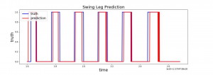
Figure 5: Swing leg Prediction
Test 3: Off person testing with swing leg prediction
For this test, the user walked wearing only the sensors, while the exoskeleton was fixed onto
a cart and actuated off person. We used the machine learning model for swing leg classification.
We compared the pitch angles measured by the IMUs on the exoskeleton’s leg link and the
user’s pitch angles measured by the IMUs attached to the user’s leg. From Figure 32, the user’s
pitch matched the exoskeleton’s pitch very well. The error of the peak value is less than 5
degrees on average. This test showed that the trajectory of the motion of the exoskeleton
matched the gait of the user.

Figure 6: User’s pitch exoskeleton’s pitch
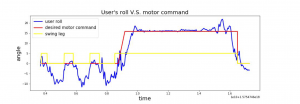
Test4: Off person testing with perturbation
In this test, we demoed our exoskeleton can react to the perturbation from the side by
actuating our adduction/abduction motor. The perturbation is generated by pulling a rope
attached to the user from the user’s side while the user is walking. Figure 33 shows the desired
motor command of the adduction/abduction motor versus the roll angle of the user’s leg. When
the perturbation happened, there was a sudden increase of the user’s roll angle, and our motor
command match that roll angle well for both the time and the scale. This demo showed that our
system reacts to perturbation correctly.