The mechanical subsystem consists of the exoskeleton frame, hip joint actuators, linkages to connect our actuator joints, leg brace to secure the exoskeleton to the user and mounts for our sensors, circuitboards and onboard computer. We have completed initial cardboard and acrylic prototypes and have used them to figure out our critical dimensions and design decisions for the form factor of the exoskeleton. We have an initial CAD design of our exoskeleton and are currently in the process of designing and manufacturing our actuator assemblies.
18 January 2019
A cardboard prototype of the exoskeleton was made to evaluate the potential formfactor and make decisions regarding critical dimensions that affect actuator joint alignments. The prototype was put on to ensure the exoskeleton did not restrain natural movement.

Fig 1: Cardboard prototype
27 January 2019
An acrylic prototype was made using the dimensions of the cardboard prototype to make refinements to the designed dimensions of the exoskeleton with a more structurally sound prototype. This design informed the decision to use tubular links as opposed to plates.
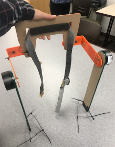
Fig 2: Acrylic prototype
Exoskeleton CAD
10 February 2019
An initial CAD of what the final exoskeleton would look like with the current design decisions was created

Fig 3: Initial CAD of Exoskeleton
Test Rig Development
20 February 2019
The main purpose of designing and fabricating a mechanical test rig was to be able to use available (brushed DC) motors and (1:20) gearboxes to actuate a subject’s leg, in order to understand how much torque needs to be provided, as well as how much reflected inertia can be tolerated, when assisting a user’s leg movement.
A draft motor shaft coupler was designed and printed in Solidworks:
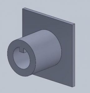
Fig 4: Draft motor shaft coupler
After ensuring proper fit, a second version was designed and printed with tougher materials:

Fig 5: motor shaft coupler version-2
A wooden block to connect to this coupler and securely house a 1” PVC pipe was then fabricated:
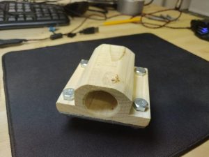
Fig 6: Wooden PVC holder
Finally, the two parts were put together to form the final motor shaft coupler.
The off-the-shelf leg brace was mounted to the leg linkage PVC pipes with a 3D printed mount.

Fig 7:CAD design of the leg brace attachment mount
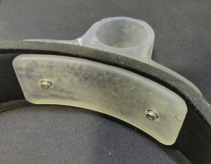
Fig 8: Finished assembly of leg brace mount to the brace
7 March 2019
On testing the coupler, we discovered that the torque required to actuate the leg were far too high for the 3D printed shaft to handle, and hence, a stronger design was developed with larger supporting dimensions and greater infill density.

Fig 9: The toughened coupler model
However, this part too, could not withstand the torques that were being produced. Hence, a new design using Aluminium was considered.
27 March 2019
The new part was fabricated by turning a solid shaft of Aluminium and milling the chambers for the PVC pipe as well as motor shaft. A keyway was drawn through with the help of a hydraulic press, and set screw holes were milled and tapped to keep the key and PVC link in place.
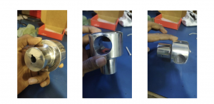
Fig 10: The mechanical test-bench’s gearbox-PVC link coupler
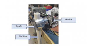
Fig 11: The coupler connected to the gearbox and PVC link
1 April 2019
A compact version of the coupler was finally designed, keeping weight and size constraints in mind.
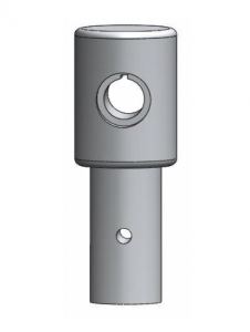
Fig 12: The new gearbox and PVC link coupler CAD model
This piece was then turned and milled, and a keyway was drawn out. For the final exoskeleton, a piece very similar to this will be used, and the only potential change would be the diameter of the lower half of the coupler, to fit into a carbon fiber pipe instead of a PVC pipe.
Actuator Design, Manufacturing, and Assembly
26 March
With the gearboxes and motors ordered, design on the actuator assembly finally began.
The current CAD, featuring our ordered Tmotors (U8 Lite) and Matex gearboxes is shown below. Machining will begin ASAP.
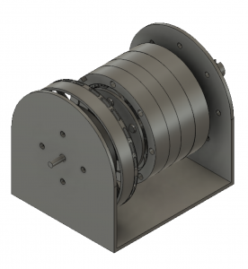
Fig 13: Initial design of the hip flexion/extension (HFE) actuator
1 April
After initial review of the actuator design, the housing design was altered to have better structural support (with the addition of spacer mounts). The new housing design can be seen the CAD below.
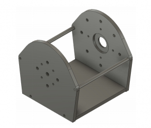
Fig 14: New actuator housing design
9 April
Over the past week, a lot of work has gone into sourcing parts, machining and assembly. The resultant actuator sub-assembly can be seen in the figures below. It successfully houses and couples our BLDC motor and planetary gearboxes, as well as provides encoder feedback with the mounted magnetic absolute encoder. Testing was done on the final assembly to validate the smoothness of motion and reflected inertia.

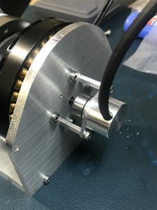
Fig 15: The finished HFE sub-assembly
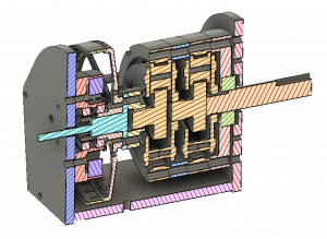
Fig 16: Cross-sectional view of the components that are within the HFE actuator.
15 April
Next, we moved on to design the exoskeleton backplate and hip adduction/abduction (HAA) actuators. The biggest challenge here was in figuring out a way to avoid the output shaft of the HAA actuator from running in to the user. This was done in the design below by having two offset backplates, one which features the belt loops that the user will use to put on the exoskeleton and the second mounts the HAA actuators.
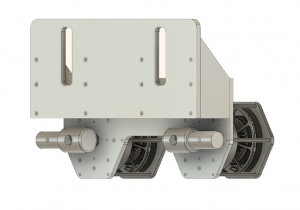
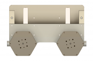
Fig 17: CAD model of the backplate and HAA actuator sub-assembly
FEA simulation was conducted to verify that the output shaft will be able to support the loads of the exoskeleton. A load of 20N was applied, from which the maximum stress the part saw was 3.3 MPa, much less than the yield strength of the material (steel: 250 MPa).

Fig 18: FEA simulation results
17 April
The complete exoskeleton CAD was assembled using custom designed couplers and PVC pipes to connect between the HFE and HAA actuators as well as for the leg linkages. Views of the complete CAD assembly can be seen below.
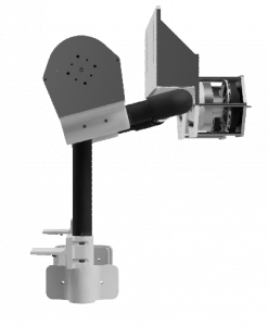

Fig 19: Front and side views of the Exoskeleton CAD.
23 April
The last week was again spent on parts sourcing and machining. The finished result was half of the exoskeleton frame, shown in mechanical testing on the user in the image below.
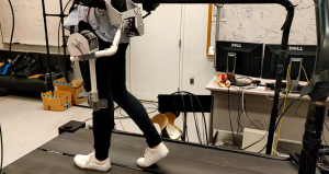
fig 20: Half of the exoskeleton frame during fit and range of motion testing
A couple things we found during testing was that the majority of the weight is concentrated toward the back and the HFE actuator does not stay in place without actuation of the HAA actuator. These are not major concerns, however, another design was conceptualized to mitigate these two concerns. This new design can be seen below.
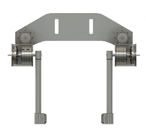
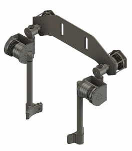
Fig 21: Alternative backplate design
This design will be tested and compared to the current exoskeleton backplate early next semester.
September 12, 2019
Second design of the exoskeleton backplate was prototyped and tested. Due to added complexity and need for a sliding joint at the thigh brace for this new design, it was decided to not go forth with it and stick with our previous backplate design.

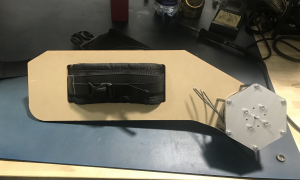
Figure 22: Second backplate design and prototype
Hardware mounting design and strap design was completed on the original backplate to go forth with manufacturing. Sheet metal was ordered.

Figure 23: CAD of the current state of the exoskeleton. The backplate has been extended to allow for the addition of another set of waist straps. A 3D printed box will be mounted to the back that will house all of our hardware components.
September 26, 2019
Last two weeks were focused on fabrication to complete machining of all parts needed for the backplate and actuators. Machined parts can be seen in figures below.
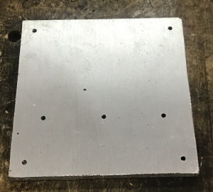

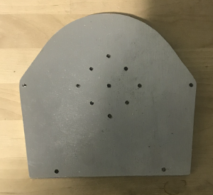
Figure 24: Four actuator plates manufactured on the CNC. The first three will make the housing of the flexion/extension actuator, the last one will be the end plate for the abduction/adduction actuator.
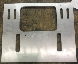
Figure 25: Finished backplate, design 2, part.
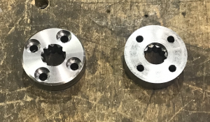
Figure 26: Motor-gearbox coupler, fabricated out of steel. Turned and faced down on the lathe, drilled and counter-bored on the mill.

Figure 27: Encoder shaft for the motor. Turned down on the lathe, drilled on mill. Two of these were machined.
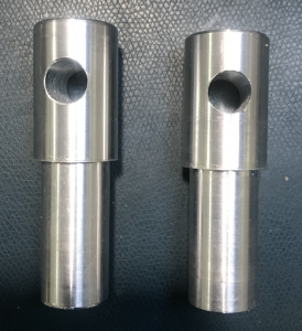
Figure 28: Actuator-leg-linkage couplers. Made out of aluminum, turned on the lathe, drilled on mill.
The backplate was assembled and straps were put on to test fit.
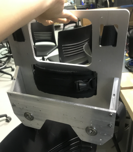

Figure 29: Assembly of the newly revised backplate design.
October 10, 2019
Hardware box parts were 3D printed and assembled. Hardware mounted inside, and then mounted to the exoskeleton. Electrical system then was integrated.

Figure 30: The finished hardware box to be mounted to the back of the exoskeleton and wired.
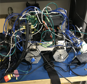
Figure 31: Electrical and Mechanical integration — baseline complete! Still needs refinement